


Installation
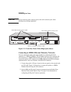
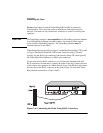
Connecting the Probe
50
CAUTION
Do not touch the probe connector pins or the cable connector pins. Static
discharge may damage equipment.
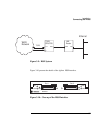
Connecting to 10MB/s Ethernet Telemetry Networks
You can connect the probe to the network either by connecting the RJ-45
connector to a 10Base-T/100Base-TX half-duplex network or by connecting the
AUI connector to a 10MB/s Ethernet network. Use the following procedures to
connect the probe’s AUI connector to a 10MB/s Ethernet network for telemetry
communications. Never use both the AUI and RJ-45 connectors.
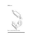
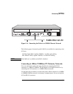
1. Connect the probe’s AUI port, located on the rear panel, to the network with
an AUI cable. Figure 3-4 shows how to connect the probe to a 10MB/s
Ethernet network using the AUI connector.
2. Select
AUI
as the Physical Connector parameter from the Modify/View
Interface Values menu. Refer to Step 1 on page 25 for information on
configuring the Physical Connector parameter.
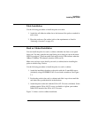
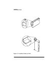
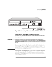
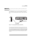
Figure 3-3: Probe Rear Panel (Token-Ring Option shown)
RS-232
Config.
Power
AUI
100Base-T
Collision
Activity
Activity
DB-9
RJ-45
Token-Ring Telemetry INTERFACE
Data
Clock
Fault
Fault
Data
Clock
Port 1
Port 2
To DTE From DCE
Token-Ring Telemetry Status LED
10Base-T/100Base-TX Status LEDs
HSSI WAN Interface Status LEDs
HSSI Interface