


U2751A User’s and Service Guide XIII
List of Figures
Figure 1-1. 25-pin male DSub connector 23
Figure 1-2. U2922A pin configuration 24
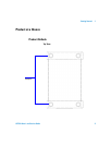
Figure 1-3. U2922A outlook 25
Figure 1-4. U2922A dimensions 26
Figure 1-5. 55-pin backplane connector pin configuration 29
Figure 2-1. Switch matrix concept 33
Figure 2-2. Panel view of the Agilent Measurement Manager 34
Figure 2-3. Panel view of the relay cycle counter 36
Figure 4-4. Defective relay(s) check 44