


U2751A User’s and Service Guide 49
Index
#
55-pin backplane connector pin, 29
A
AC
characteristics, 41
AC/DC power adapter
output voltage, 15
requirements, 15
Agilent Measurement Manager
help file, 2, 22
installation, 13, 14
launching, 21, 22
operation, 34, 36, 37, 37
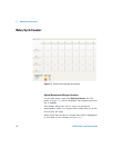
panel view, 34
relay cycle count, 44, 47
welcome screen, 22
Agilent Modular Products Installation Menu
Hardware Driver, 12
Measurement Manager, 13
Agilent U2751A USB Modular Switch
Matrix,
dialog box, 12
Quick Reference Card, 7
B
bandwidth, 41
bumper, 8
bumper casing, 8, 30
browser, 10
C
*CLS, 35, 38
carrier board, 46, 47
Certificate of Calibration, 7
channel label, 33
channels, multiple
chassis
configuration, 2
installation, 30
cleaning, general, 8
column, 2, 23, 33, 34, 35, 44
configuration, instrument
connector, 23
pin assignments, 23
55-pin backplane connector pin, 29
cross-point, 2
D
DC
isolation, 41
output plug, 15
defective relays, check, 44
DIAGnostic:RELay:CYCLes?
(@<ch_list>), 44
device under test. See DUT
disassembly. See relays, replacing
DSub connector, 23, 44
DUT, 2
E
electrical check, 8
electrostatic discharge. See precautions
error conditions
Agilent Measurement Manager
operation, 37
SCPI Commands, 38
F
firmware, 18, 19
flowchart, 9
G
GND, 23, 29
I
*IDN, 20
I/O cable, 8
inspection, initial, 8
installation
Agilent Measurement Manager, 13
connecting the module, 15
IO Libraries Suite, 11
launching the Agilent Measurement
Manager, 21
module driver, 12
system check, 10
verifying the module connection, 20
introduction
U2751A USB modular switch matrix, 2
IO Control, 11, 21
IVI-COM driver, 9
L
LED indicators, 32
L-Mount kit, 7, 30
M
matrix, V, VIII, 2, 7, 12, 33, 34
maintenance, general, 8
measurement board, 46, 47
Microsoft
®
Internet Explorer. See browser
modular instrument chassis, 7, 29
modular switch matrix. See introduction
module driver. See installation