


Operation and Features 2
U2751A User’s and Service Guide 33
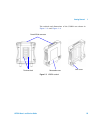
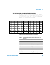
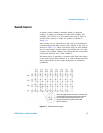
Switch Control
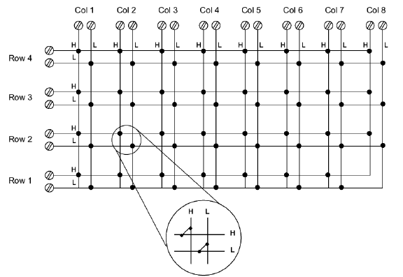
A matrix switch connects multiple inputs to multiple
outputs. A matrix is arranged in rows and columns. For
example, the U2751A is a 48 matrix that can be used to
connect four sources to eight test points as shown in
Figure 2-1.
Any column can be connected to any row by activating the
corresponding relay that connects the column to the row as
shown in Figure 2-1. Each cross-point relay on this module
has its own unique channel label representing the row and
column. For example, channel 302 represents the cross-point
connection between row 3 and column 2.
Be aware that it is possible to connect more than one source
to the same point with a matrix. It is vital to make sure that
these connections do not create dangerous or unwanted
conditions.
Note: Three-digit channel numbers are derived from
the intersection of the rows and columns, with the
last two digits representing the columns. The
intersection shown represents channel 202
(Row 2, Column 2)
Figure 2-1 Switch matrix concept