


Albatron Anniversary Special Edition PX845PEV-800
15
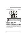
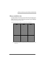
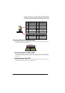
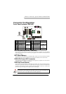
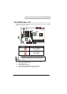
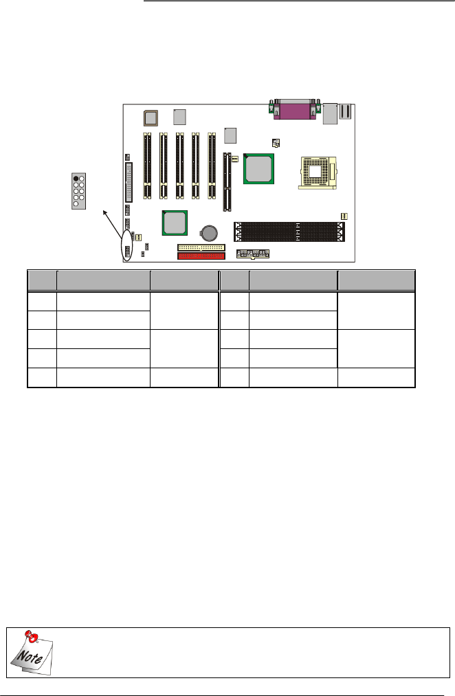
Connector Configuration
Front Panel Indicator: SW/LED
HD LED (Hard Drive LED Connector)
This connector can be attached to an LED on the front panel of a computer case. The LED will
flicker during disk activity. This disk activity only applies to those IDE drives directly attached
to the system board.
RST (Reset Button)
This connector can be attached to a momentary SPST switch. This switch is normally left open.
When closed it will cause the mainboard to reset and run the POST (Power On Self Test).
PWR-LED (Power LED Connector)
This connector can be attached to an LED on the front panel of a computer case. The LED will
illuminate while the computer is powered on.
PWR ON (Power Button)
This connector can be attached to a front panel power switch. The switch must pull the Power
Button pin to ground for at least 50 ms to signal the power supply to switch on or off (the time
required is due to internal debounce circuitry on the system board). At least two seconds must
pass before the power supply will recognize another on/off signal.
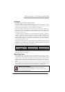
Pin Assignment Function Pin Assignment Function
1
HD LED (+) Hard Drive
2
Power LED (+) POWER
3
HD LED (-) LED
4
Power LED (-) LED
5
Reset Control (-)
Reset
6
Power Button(+) Power-on
7
Reset Control(+)
Button
8
Power Button(-) Button
9
NC NC
10
NC NC
This mainboard complies with the ATX standard, which means the ACPI connector
on this board is 2-pin. If the Power LED cable of your case uses a 3-pin adapter, you
must use the 2-pin to 3-pin adapter (Please read the Appendix II).
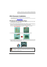
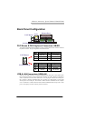
Socket 478
Intel
82801DB
U6
U17
BAT1
JP1
CASE OPEN
SPEAKER
SW/LED
USB2 USB3
Phoenix
Bios
KB/MS
USB/LAN
IrDA
PCI3
PCI5
LAN
CHIP
PCI4
Intel
82845PE
U10
AGP
PCI2
ATX_P WR
FDC
IDE1IDE2
PRT/COM
Win bond
W83627HF
ATX_ 12 V
PCI1
CPUFAN
AUXFAN
CHASFAN
DIMM1
DIMM2
DIMM3
1++
+
+
-
--
-
2
34
56
78
910
SW/LED