Hardware Overview
Except on the first page, right running head:
Heading1 or Heading1NewPage text (automatic)
11
Alcatel-Lucent
Beta Beta
OmniAccess 740 Hardware User’s Guide
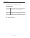
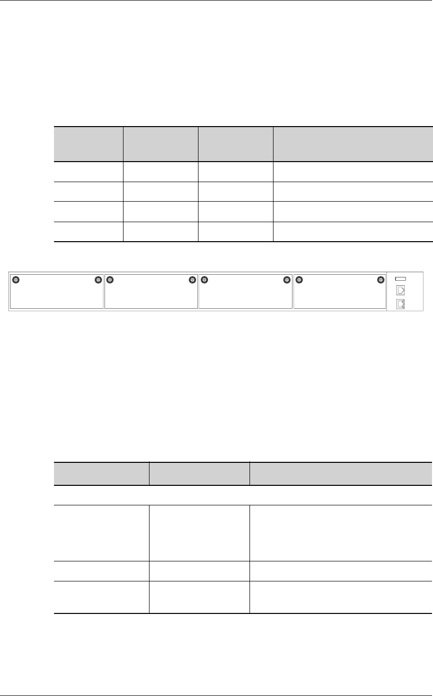
SLOT NUMBERS
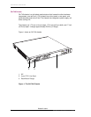
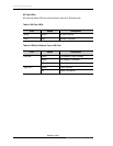
The slots in the front panel are numbered 0 through 3, from left to right.
The table below lists the slot number and the component associated with it.
Table 2: Slot Numbers
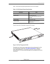
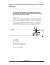
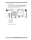
Figure 5: OA-740 (4-Slot Chassis)
LED I
NFORMATION
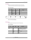
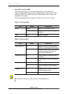
The following table shows the state of the main LEDs after startup.
Table 3: LED Status
Slot Number Location Slot Type
Card Associated With the Slot
Number
0 Front Panel Single Line Card
1 Front Panel Single Line Card
2 Front Panel Dual SE
3 Front Panel Dual SE
LED Status Description
SE LEDs
Active Off Power up status. This is the default
display when the system is first
powered on and before the software is
loaded.
Green SE card is active.
Yellow Indicates transient conditions (e.g.,
booting).
OmniAccess
740
USB Modem Console
0123


