


AT-2911GP Gigabit Fiber Ethernet PoE+ Adapters Installation and User’s Guide
34
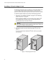
Connecting the Network Cables
The AT-2911GP adapter card is equipped with the fiber optic and PoE+
copper ports. The fiber optic port is for the network; the PoE+ copper port
is for a PoE Powered Device (PD), such as a VoIP phone. To connect the
adapter card to the network and PD, you must have a fiber optic cable with
the appropriate connecter and a twisted-pair copper cable.
Connecting a
Fiber Optic
Network Cable
To connect a fiber optic network cable to the adapter, perform the
following procedure:
1. Prepare a fiber optic cable with an appropriate connecter.
Warning
The fiber optic ports contain a Class 1 laser device. When the ports
are disconnected, always cover them with the provided plug.
Exposed ports may cause skin or eye damage.
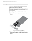
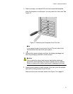
2. Remove a rubber plug from the adapter.
3. Connect one end of the cable to the adapter.
4. Connect the other end of the cable to the appropriate Ethernet network
port or fiber optic port.
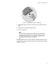
Note
After the cable is properly connected at both ends, the adapter card
LED should be functional. See Table 1 on page 17 for a description
of LED operation.
Connecting a
Twisted-Pair
Copper Cable
To connect a twisted-pair copper cable to the adapter, perform the
following procedure:
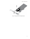
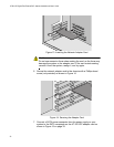
1. Prepare a twisted-pair copper cable.
2. Connect one end of the cable to the adapter.
3. Connect the other end of the cable to a PD, such as a VoIP phone.
Note
After the cable is properly connected at both ends, the adapter card
LED should be functional. See Table 1 on page 17 for a description
of LED operation.