


Chapter 1: Overview
12
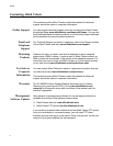
Model Descriptions
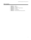
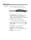
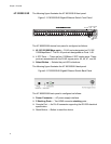
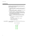
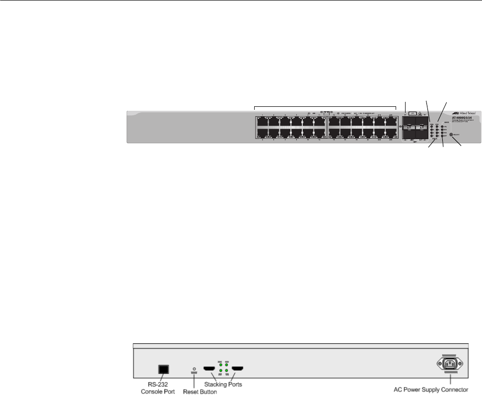
AT-8000GS/24 The following figure illustrates the AT-8000GS/24 front panel.
Figure 1 AT-8000GS/24 Gigabit Ethernet Switch Front Panel
The AT-8000GS/24 front panel is configured as follows:
24 10/100/1000Mbps ports — RJ-45 ports designated as 10/100/
1000Base-T. The RJ-45 ports are designated as Ports 1-24.
4 SFP Ports — There are four 1000Base-X SFP combo ports. These
ports are associated with the RJ-45 copper ports: 21, 22, 23 and 24.
Select Button — Selects the port LED indications.
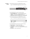
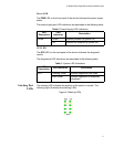
The following figure illustrates the AT-8000GS/24 back panel.
Figure 2 AT-8000GS/24 Gigabit Ethernet Switch Back Panel
The AT-8000GS/24 back panel is configured as follows:
Power Connector — AC power supply interface.
2 Stacking Ports — Two HDMI connector stacking ports .
Console Port — An RJ-45 connector supporting the RS-232 electrical
specification.
Reset Button — Button to reset the device.
1336
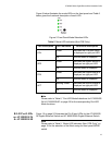
SFP Ports
Mode
Button
Mode
LEDs
10/100/1000Base-T Ports
Power
LED
LED
Stacking
LEDs
10/100/1000Base-T Ports10/100/1000Base-T Ports
Diagnostic