


Chapter 1: Product Description
14
Components
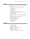
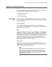
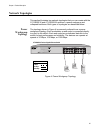
Figure 1 illustrates the front panels of the AT-GS900/16 and AT-GS900/24
switches.
Figure 1. Front Panels
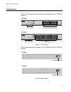
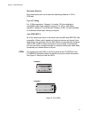
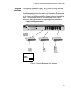
Figure 2 illustrates the back panels of the AT-GS900/16 and AT-GS900/24
switches.
Figure 2. Back Panels
16 - 10/100/1000Base Twisted Pair Ports
600
System / Port LEDS
AT-GS900/16
AT-GS900/24
24 - 10/100/1000Base Twisted Pair Ports
601
System / Port LEDS
100-240VAC
602
AC Power Connector
AT-GS900/16
AT-GS900/24
100-240VAC
603
AC Power Connector