


AT-GS900/16, AT-GS900/24 Fanless Gigabit Ethernet Switches Installation Guide
17
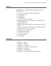
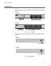
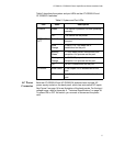
Table 2 describes the system and port LEDs on the AT-GS900/16 and
AT-GS900/24 switches.
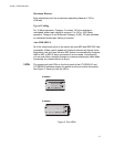
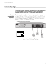
AC Power
Connector
Both the AT-GS900/16 and AT-GS900/24 switches have a single AC
power supply socket on the back panel, which has auto-switch AC inputs.
See Figure 2 on page 14 for an illustration of the back panels. For the input
voltage range, refer to Appendix A, ”Technical Specifications” on page 38.
To power ON or OFF the switch, you connect or disconnect the power
cord.
Table 2. System and Port LEDs
LED State Description
POWER Green The switch is powered ON and operating
normally.
OFF The switch has no power.
SPD/LINK/
ACT
Solid Green A valid 1000 Mbps link is established on
the port.
Solid
Orange
A valid 10 or 100 Mbps link is
established on the port.
Blinking
Green
A 1000 Mbps packet transmission and
reception is in process on the port.
Blinking
Orange
A 10/100 Mbps packet transmission and
reception is in process on the port.
OFF No link is established on the port.
FDX/HDX Solid Green A full-duplex link is established on the
port.
OFF A half-duplex link is established on the
port.