


AT-GS900/16, AT-GS900/24 Fanless Gigabit Ethernet Switches Installation Guide
33
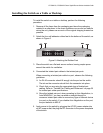
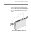
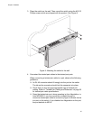
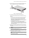
5. Mount the switch in the 19-inch rack using the #10-32 Phillips screws
which are shipped with the product, as illustrated in Figure 11.
Figure 11. Rackmounting the Switch
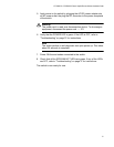
6. Connected the twisted pair cables to the twisted pair ports.
When connecting a twisted pair cable to a port, observe the following
guidelines:
An RJ-45 connector should fit snugly into the port on the switch.
The tab on the connector should lock the connector into place.
Check that you are using the appropriate type of twisted pair
cabling. Refer to “Twisted Pair Cabling and Distances” on page 25
for twisted pair cable specifications.
Since the twisted pair port, when operating in Auto-Negotiation, is
Auto MDI/MDI-X, you can use either a straight-through or
crossover twisted pair cable to connect any type of network device
to a port on the switch. If you disable Auto-Negotiation on the port,
the port defaults to MDI-X.
7. Apply power to the switch by plugging the AC/DC power adapter into
an AC power outlet, the plug the DC connector to the power receptacle
of the switch.
Warning
The power cord is used as a disconnection device. To de-energize
equipment, disconnect the power cord. E3
8. Verify that either the POWER LED is green. If the LED is OFF, refer to
“Troubleshooting” on page 37 for instructions.
Note
The switch perform a self-diagnostic test upon power up. This takes
about 20 seconds to complete.
606