


AT-GS900/16, AT-GS900/24 Fanless Gigabit Ethernet Switches Installation Guide
35
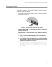
Cabling the Switch
To connect to the ports on the AT-GS900/16 and AT-GS900/24 switches,
perform the following procedure:
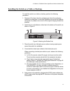
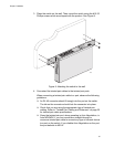
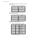
1. Connect the twisted pair data cables to the RJ-45 ports on the switch,
as illustrated in Figure 12.
Figure 12. Connecting the Twisted Pair Data Cables
2. Power on the end-nodes. For more information, refer to “Powering On
the Switch” on page 36.
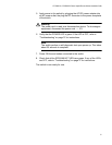
When connecting a twisted pair cable to a port, observe the following
guidelines:
An RJ-45 connector should fit snugly into the port on the switch.
The tab on the connector should lock the connector into place.
The ports on the switch are auto-MDI/MDI-X. You can use either a
straight-through or crossover twisted pair cable to connect any type
of network device to a port on the switch.
The network should not contain data loops, which can adversely
affect network performance. A data loop exists when two or more
network devices can communicate with each other over more than
one data path.
613