


Appendix A: Technical Specifications
40
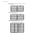
Table 4 lists the RJ-45 pin signals when a twisted pair port is operating in
the MDI configuration.
Table 5 lists the RJ-45 port pin signals when a twisted pair port is
operating in the MDI-X configuration.
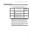
Table 6 lists the RJ-45 connector pins and their signals when a
1000Base-T port is operating at 1000 Mbps.
Table 4. MDI Pin Signals (10Base-T or 100Base-TX)
Pin Signal
1TX+
2TX-
3RX+
6RX-
Table 5. MDI-X Pin Signals (10Base-T or 100Base-TX)
Pin Signal
1RX+
2RX-
3TX+
6TX-
Table 6. RJ-45 1000Base-T Connector Pinouts
a
a. Bi-directional data on each pair.
Pin Pair Signal
1 1 TX and RX+
2 1 TX and RX-
3 2 TX and RX+
4 3 TX and RX+
5 3 TX and RX-
6 2 TX and RX-
7 4 TX and RX+
8 4 TX and RX-