


AT-GS900/16, AT-GS900/24 Fanless Gigabit Ethernet Switches Installation Guide
27
Installing the Switch on a Table or Desktop
To install the switch on a table or desktop, perform the following
procedure:
1. Remove all the items from the packaging and store the packaging
material in a safe place. In the event a problem occurs and you need to
return the unit, please use as much of the original shipping material as
possible.
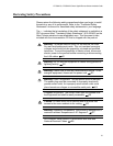
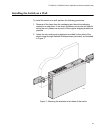
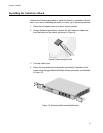
2. Attach the four self-adhesive rubber feet to the bottom of the switch, as
shown in Figure 6.
Figure 6. Attaching the Rubber Feet
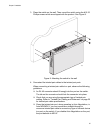
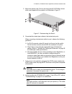
3. Place the switch on a flat and secure surface, leaving ample space
around the switch for ventilation.
4. Connected the twisted pair cables to the twisted pair ports.
When connecting a twisted pair cable to a port, observe the following
guidelines:
An RJ-45 connector should fit snugly into the port on the switch.
The tab on the connector should lock the connector into place.
Check that you are using the appropriate type of twisted pair
cabling. Refer to “Twisted Pair Cabling and Distances” on page 25
for twisted pair cable specifications.
Since the twisted pair port, when operating in Auto-Negotiation, is
Auto MDI/MDI-X, you can use either a straight-through or
crossover twisted pair cable to connect any type of network device
to a port on the switch. If you disable Auto-Negotiation on the port,
the port defaults to MDI-X.
5. Apply power to the switch by plugging the AC/DC power adapter into
an AC power outlet, the plug the DC connector to the power receptacle
of the switch.
606