


7
SECTION III
INSTALLATION PROCEDURES
Installation should be performed by competent technicians in accordance with local and state codes. In the
absence of these codes, the installation must conform to applicable American National Standards: ANSI
Z223.1-LATEST EDITION (National Fuel Gas Code) or ANSI/NFPA NO. 70-LATEST EDITION (National
Electrical Code) or in Canada, the installation must conform to applicable Canadian Standards: CAN/CGA-
B149.1-M91 (Natural Gas) or CAN/CGA-B149.2-M91 (Liquid Propane [L.P.] Gas) or LATEST EDITION
(for General Installation and Gas Plumbing) or Canadian Electrical Codes Parts 1 & 2 CSA C22.1-1990 or
LATEST EDITION (for Electrical Connections).
A. UNPACKING/SETTING UP
Remove protective shipping material (i.e., plastic wrap, and/or optional shipping box) from dryer.
NOTE: The access keys for the service doors are included in the information packet shipped in the
basket (tumbler). These keys should be removed and put in a safe place, yet made
accessible because some will be needed throughout various phases in the installation of the
dryer.
Dryers are shipped with a coin box and coin box faceplate ONLY. The coin box lock is not included and
must be purchased elsewhere, or the lock can be ordered as a parts order from the ADC factory.
IMPORTANT: For shipping purposes, the 10-inch (25.40 cm) exhaust adapter is shipped inside one
(1) of the dryer’s baskets (tumblers). This exhaust adapter should either be left
inside the basket (tumbler) or removed and put in a safe place, and must be installed
once the dryer is in place prior to making any exhaust duct connections.
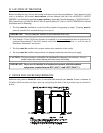
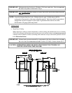
The dryer can be moved to its final location while still attached to the skid or with the skid removed. With the
skid removed, to make it easier to slide the dryer into its final position, slightly lower ALL four (4) leveling legs,
so that the dryer will slide on the legs instead of the base frame. The dryer is equipped with four (4) leveling legs,
one (1) at each corner of the dryer base. The legs can be adjusted by either tilting and properly supporting the
dryer, and adjusting from underneath with an open end wrench (or adjustable wrench). Or, by removing the rear
lower back panel and/or front lower service panel and adjusting the leveling leg with a 1/4” socket.
IMPORTANT: When tilting the dryer to adjust the leveling legs, be sure to properly support the
bottom of the dryer with a block of wood or similar object. Failure to do so can
cause personal injury!