


20
3. Piping Connections
ALL components/materials must conform to National Fuel Gas Code Specifications ANSI Z223.1-LATEST
EDITION, or in Canada, CAN/CGA-B149.1-M91 (Natural Gas) or CAN/CGA-B149.2-M91 (Liquid
Propane [L.P.] Gas) or LATEST EDITION (for General Installation and Gas Plumbing), as well as local
codes and ordinances and must be done by a qualified professional. It is important that gas pressure
regulators meet applicable pressure requirements, and that gas meters be rated for the total amount of
ALL the appliance Btus being supplied.
The size of the main gas supply line (header) will vary depending on the distance this line travels from the
gas meter (or in the case of L.P. gas, the supply tank), the number of tees, other gas-operated appliances
on the supply line, etc. Specific information regarding supply line size should be determined by the gas
supplier.
NOTE: Undersized gas supply piping can create a low or inconsistent pressure which will result in
erratic operation of the burner ignition system.
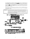
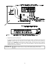
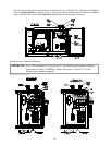
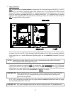
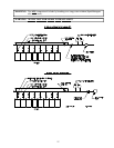
Consistent gas pressure is essential at ALL gas connections. It is recommended that a 3/4” (19.05 mm)
pipe loop be installed in the supply line servicing the bank of dryers. An in-line pressure regulator must be
installed in the gas supply line (header) if (natural) gas line pressure exceeds 12.0 inches (29.9 mb) water
column (W.C.) pressure. (Refer to the illustrations on page 21 for details.)
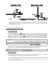
IMPORTANT: Water column pressure of 3.5 inches (8.7 mb) for natural gas dryers and 10.5 inches
(26.1 mb) for L.P. gas is required at the gas valve pressure tap of each dryer for
proper and safe operation.
A 1/8” N.P.T. plugged tap, accessible for a test gauge connection, must be installed in the main gas supply
line immediately upstream of each dryer.
IMPORTANT: Pipe joint compounds that resist the action of natural gas and L.P. gas must be used.