


MX28B1200/2400 MX28B1200/4800 –48 VDC User’s Manual Page 9
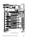
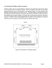
Fuse Alarm Ribbon Cable Connections
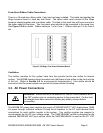
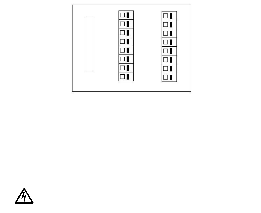
There is a 16-conductor ribbon cable, if any bay has fuses installed. This cable ties together the
Wago breakout board in each bay with fuses. The ribbon cable must connect all the Wago
breakout boards together with one ribbon cable. The idea is that each fuse will have one wire in
the ribbon cable for the alarm. Two fuse alarm wires should not be connected to the same fuse.
See Figure 3.2-6 for details. Ribbon cable pin 1 is for Fuse 1. Ribbon cable pin 2 is for Fuse 2
etc.
Figure 3.2-6 Wago Fuse Alarm Breakout Board
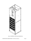
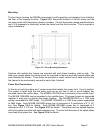
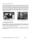
Ventilation
The rectifier modules for this system have fans that provide front-to-rear airflow for internal
cooling. The MX28B housing should mounted such that there is free airflow to the front and top
of the unit. [Refer to Section 8.5 for environmental characteristics.] Free airflow should be
ensured so that the power system can provide full power without de-rating.
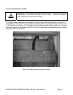
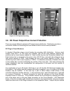
3.3. AC Power Connections
WARNING: Ensure that all of the external DC and AC circuit breakers are in
the OFF position prior to connecting service to the power plant. Confirm that
all voltages have been removed including any battery sources before
proceeding
.
The MX28B DC power plant requires the supply of 208/220/240/277 VAC single-phase, 50/60
Hz power through individual external 20-amp circuit breakers to the AC input terminal block
connections for each rectifier module in the system. Two rectifier modules are required to
accommodate the full AC input voltage range. The 1MRF28H54BV rectifier is designed for the
standard 208/220/240 VAC input service, while the 1MRF28H54BV50 is used for the 277 VAC