


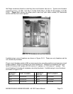
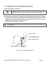
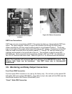
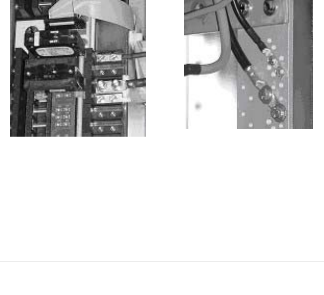
Figure 3.8-1 Load connections for snap-in
breakers
Figure 3.8-2 Return Connections
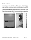
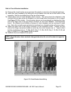
GMT Fuse Connections
GMT fuses are only connected to -48VDC if the system has been purchased with the GMT fuse
option. This option supplies -48VDC to lugs on the interface card through #6 AWG power
cables controlled by a 50 Amp circuit breaker located in circuit breaker Position 1. The 2-hole
lugs on both ends of the power cables have #10 holes on 5/8” centers. Connections to the GMT
fuses are made at terminal block connectors labeled “F1” through “F8” that are located on the
interface card mounted in the top left side of the unit. The connector is sized to accept #12 –
#28 AWG wire. Each connector has two positions, labeled “-48V” and “RTN”, for connection of
the -48V DC load and load return wires. Refer to Figure 3.9-1 for Interface board connections.
NOTE: The controller will not report GMT Fuse failures in the MX28B1200 system. Only
telecom style fuses can be monitored. Use GMT fuses only in non-essential
applications.
3.9. Monitoring and Relay Output Connections
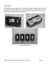
Front Panel DB9 Connection
The front panel DB-9 connector is for use by the factory only. Do not hook up the special RS-
232 cable (APC part number 940-0024C). This cable is only to be used with the DB-9 near the
Web/Simple Network Mail Protocol (Web/SNMP) card.
“Smart” Cable DB9 Connection