


Symbols Used In This Manual
The following symbols appear in this User's Manual:
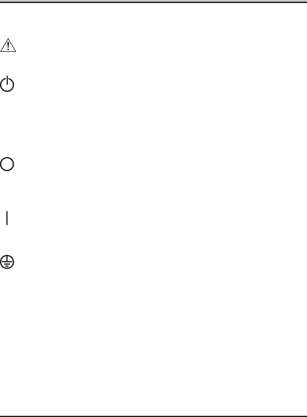
CAUTION/DANGER - Caution indicates risk of
bodily harm. Danger indicates that a risk of elec-
trical shock is present and the associated proce-
dures should be followed carefully.
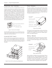
“STAND BY MODE” - The system enable switch,
and the input circuit breaker use the “stand by”
mode. When either of these are switched to “stand
by,” the Power Array is disconnected from utility
input voltage. In this mode, the system appears to
be off, although the utility power is still connected
to the system. For this reason, the standby mode
is unsafe for servicing the system. Always follow the
five step Total Power Off procedure before servic-
ing the Power Array. (See procedure at right.)
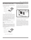
“OFF POSITION” - The maintenance bypass
switch is the only switch that can be placed in the
“off” position. When switched to the “off” posi-
tion, the Power Array functions normally, receiv-
ing power from the utility source, and delivering
conditioned power to the load equipment.
“ON POSITION” - All three switches (The sys-
tem enable switch, the maintenance bypass switch
and the input circuit breaker) can be placed in the
“on” position. See the description for each of these
switches in chapter 1.
SAFETY EARTH GROUND - Indicates the pri-
mary safety ground.
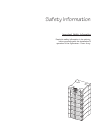
Safety
Safety-1
IMPORTANT SAFETY INSTRUCTIONS
n SAVE THESE INSTRUCTIONS - This manual contains
important instructions that should be followed during
installation and maintenance of the Power Array, and for
installation or replacement of the battery and power mod-
ules.
CONSERVER CES INSTRUCTIONS. CETTE NOTICE
CONTIENT DES INSTUCTIONS IMPORTANTES
CONCERNANT LA SÉCURITÉ.
n Connection to the branch circuit (mains) must be per-
formed by a licensed electician.
n Installation of the power and battery modules can be per-
formed by any individual with no previous technical ex-
perience.
n Operation of the equipment can be performed by any
individual with no previous technical experience.
n The protective earth conductor for the Symmetra
TM
car-
ries the leakage current from the load devices (computer
equipment). Therefore, the size of the conductor must be
at least as large as the wire required by IEC 950. IEC 950
states the following nominal cross-sectional areas:
- 2.5 mm
2
for rated current between 17 & 25 A
- 6 mm
2
for rated current between 33 & 40 A
- 10 mm
2
for rated current between 41 & 63 A
- 16 mm
2
for rated current between 64 & 80 A
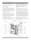
n FIVE STEP TOTAL POWER OFF PROCEDURE
To remove all power from the Power Array (Total Power
Off), the following series of events must occur in the or-
der listed:
1. Set system enable switch to the “stand by” position.
2. Set input circuit breaker to the “stand by” position.
3. Remove all battery modules from the Power Array.
4. Disconnect external battery cabinet (if present).
5. Disconnect the mains/branch circuit breaker.