


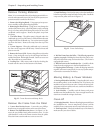
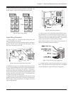
Input Wiring
n Verify that all incoming line voltage (utility power)
and low voltage (control) circuits are de-energized, and
locked out before installing cables or making connec-
tions, whether in the junction box or to the
Symmetra
TM
Power Array.
n Always verify that all battery modules are removed
and all battery extension frames are disconnected from
the Power Array before installing any wiring to the
Power Array.
n Read this chapter completely before installing any wir-
ing to the Power Array.
Input Wiring Specifications
The Power Array requires either a single phase 208V, 50/60Hz,
or a 240V, 50/60Hz incoming utility power source. A 3-con-
ductor cable (2 live, 1 ground) is to be brought to the input
wiring terminal block inside an adequate length of flexible
metal conduit. To minimize disturbances caused by other
loads in the building, input wiring should be supplied di-
rectly from the service entrance (a dedicated power feeder).
All electrical service, both input and output, must be sized in
accordance with the NEC and any local building codes. The
circuit for input power must be adequate to carry the full
load of the system and the load equipment. The 3-conduc-
tor input cable should be sized for no more than 3% voltage
drop. A 3/4” knockout in the input wiring access panel pro-
vides access to the terminal block.
See table 4-1 for input wiring specifications.
4-2
Chapter 4 - Electrical Requirements and Procedures
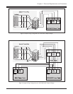
Input Wiring Procedures
An input voltage jumper must be manually set before input
wiring can be installed. Follow the procedure below:
Voltage Jumper Procedure
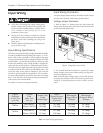
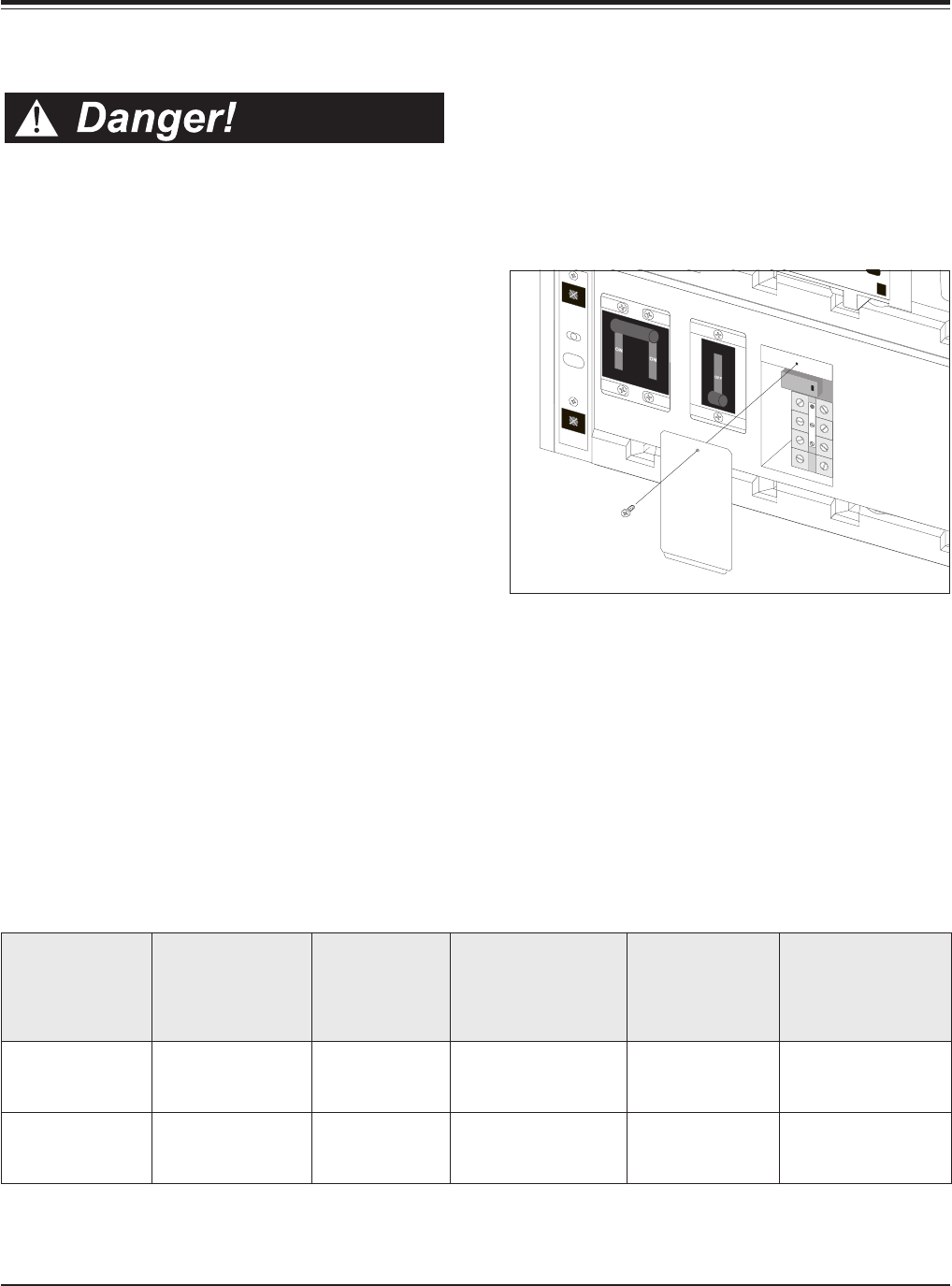
1. Refer to figure 4-1. Remove the screw that secures the
voltage select access panel to the frame. Place the screw and
access panel aside temporarily.
Fig 4-1 Voltage Select Access Panel
2. Use a small, flat head screwdriver to position the input
voltage jumper to the correct voltage setting. See figure 4-2.
Do not overtighten screws.
Note: When the input voltage jumper is in the 240V position,
the jumper bar activates a micro switch at the top of the termi-
nal block. In the 208V position, the micro switch is not acti-
vated.
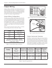
tupnI
egatloV
sulperiw-2(
)dnuorg
emarF
eziS
AVk.xaM(
)gnitaR
lluFtupnI
daoL
egarepmA
tupnI
tnerrucrevO
noitcetorP
)lanretxE(
muminiM
eriWtupnI
eguaG
muminiM
eriWdnuorG
eguaG
caV802
)AVk8(iniM
)AVk61(retsaM
pmA04
pmA08
pmA05
pmA001
eguaG8#
eguaG3#
eguaG8#
eguaG3#
caV042
)AVk8(iniM
)AVk61(retsaM
pmA53
pmA07
pmA05
pmA001
eguaG8#
eguaG3#
eguaG8#
eguaG3#
Table 4-1 Input Wiring Specifications