


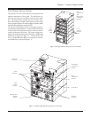
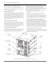


Rear View of a Power Array
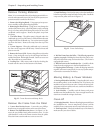
The rear of a MiniFrame system is displayed below. The rear
of a MasterFrame is similar. Each of the components are
described in a section that follows:
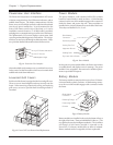
System Enable Switch
The system enable switch regulates internal power to the Power
Array. It does not power the load. When switched to the “on”
position, the Power Array enters the load-disconnect operat-
ing mode. When switched to “stand by” the Power Array is
disconnected from incoming utility voltage. The load is not
powered until the “power the load” command is entered into
the PowerView interface.
Communication Interface Ports
The following three communication ports are provided: A
remote PowerView cable port; an APC PowerChute Plus soft-
ware interface port, and two battery extension frame com-
munication ports. A 20’ RJ45 cable is provided with the Power
Array for remote installation of the PowerView.
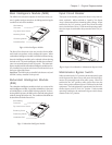
Smart Slots
TM
Accessory Ports
APC manufactures a set of auxillary user interface accessories,
called SmartSlot
TM
devices. Four SmartSlot
TM
installation ports
are provided. SmartSlot
TM
interface options include:
n Protection and safe shutdown of multiple servers
n SNMP adaptor for accessing data via a network
n CallUPS
TM
- Initiates telephone notification of power event
n MeasureUPS
TM
- monitoring environmental conditions
n Control and monitor via modem
Note: Use only SmartSlot
TM
devices labelled “Symmetra
TM
compatible.”
REPO/Input/Output Wiring Access Panels
Wiring terminal blocks for input and output wiring, and for
remote emergency power off (REPO) switch intallations are
accessed through these panels. For use by a licensed electrian.
Power Distribution Unit Panel (Optional)
An optional power distribution unit provides output power
receptacles and corresponding circuit breakers. The MiniFrame
PDU provides one L6-30R receptacle (208V), two 5-15R recep-
tacles (120V), and two L14-30R receptacles (120V/240V). The
MasterFrame PDU provides three L6-30R receptacles, four 5-
15R receptacles, and three L14-30R receptacles. The PDU panel
for both frame sizes are equipped with a panel circuit breaker.
Battery Extension Frame Connector
An optional Battery Extension Frame can be connected to the
Power Array using this coupler. See the User’s Manual inluded
with the Battery Extension Frame.
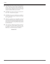
Fig 1-8 Rear View of a Mini Frame Symmetra
TM
Power Array System
SmartSlot
TM
Accessory
Ports
MiniFrame
Input
Wiring
Access
Panels
Communication
Interface
Ports
Output
Wiring
Access
Panels
Battery
Extension
Frame
Connector
System
Enable
Switch
1-4
Chapter 1 - Physical Representation
REPO Wiring
Access Panels
Power Distribution
Unit (Optional)