


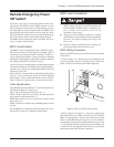

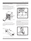

q 6. Using the PowerView display, read and record the re-
ported input voltage from the startup screen. (“122Vin”
in figure 4-16 indicates that the input voltage is 122V.)
Note: The PowerView may display one or more messages
such as “Number of Battery Modules Changed.” Press the
ESC key until the startup screen appears.
Record the PowerView reported
input voltage here: ______________________________
Fig 4-16 Startup Screen
q 7. Compare the RMS input voltage measurement (Step
#2) with the input voltage as reported by the PowerView.
If the reported input voltage is not within +/-5% of the
recorded input voltage, check the wiring, and measure
the input voltage again. If the two measurements are
still outside of the acceptable range, contact APC
Symmetra
TM
technical support at 1-888-809-TECH.
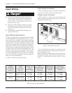
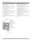
q 8. Switch the maintenance bypass switch to the “on”
position. The Power Array will go into the manual by-
pass mode, and voltage should now be present at the
output terminal connections. The bypass LED on the
PowerView display will glow, and an audible alarm may
sound, and one or more messages may appear. Ignore
these messages by pressing the ESC navigation key on
the PowerView display, until the startup screen reappears.
See figure 4-16. Read and record the output voltage that
is indicated on the PowerView. (“000Vout” in figure 4-
16 indicates that the output voltage is 000V.)
Note: The reported output voltage should be approxi-
mately 208V or 240V, depending on how the system is con-
figured.
Record the PowerView reported
output voltage here: _____________________________
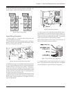
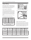
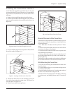
q 9. Measure the output AC voltage at the output wiring
terminal block connections as specified in table 4-4 be-
low. Record the measured values in the table. The mea-
sured values should correspond to the nominal values
listed in the table. If the input voltage varies from 208V
or 240V, the output voltages vary accordingly. In this
case, use the multipliers in table 4-4 to calculate the ex-
pected output voltages. If these voltages still vary, con-
tact Symmetra
TM
technical support at 1-888-809-TECH.
q 10. Successful completion of steps 1 through 9 indicate
that Power Array is correctly wired to the utility power
source, and that the correct output voltage is available at
the output terminal block. Load equipment voltage re-
quirements and external wiring voltages can be checked
and verified at this time.
q 11. Shut down the Power Array by switching the input
circuit breaker and the system enable switch to the “off”
position. Replace all wiring access panels on the Power
Array frame. The electrical connections have now been
properly installed and checked. The Power Array is now
ready for the setup procedure in chapter 5.
slanimreT
lanimoN
egatloV
derusaeM
eulaV
nodesaB(sreilpitluM
)noitisoPrepmuJegatloV
reilpitlum*)derusaem(niV=)derusaem(tuOV
noitisoPV802 noitisoPV042
6&2caV04251.110.1
6&4caV8020.1668.
8&2caV021675.5.
8&6caV021675.5.
01&8caV0stloV0stloV0
Table 4-4 Input/Output Measured Voltage Multipliers
Chapter 4 - Electrical Requirements and Procedures
4-9