


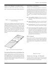

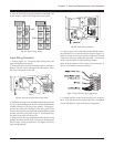
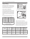
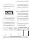
Fig 4-4 Input Wiring Pathway
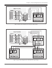
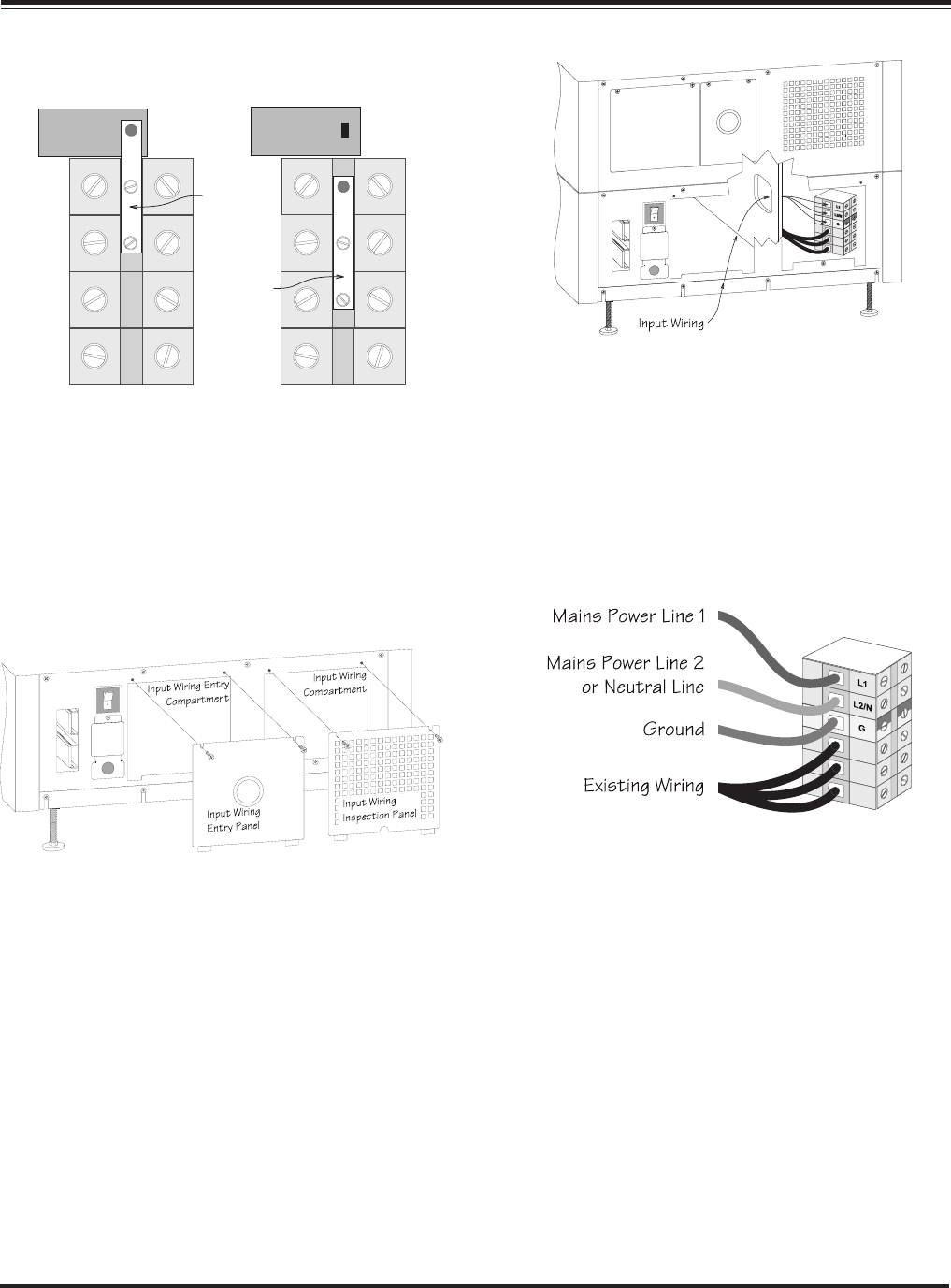
4. Connect input wires to the input terminal block connec-
tions labelled L1, L2/N and Ground as shown in figure 4-5.
Make sure there are no loose strands and that the terminal
connection screws are sufficiently tightened. Connections
are the same for 208V or 240V incoming voltages.
Note: In North America, L2/N is a phase (hot) connection. In
Europe, L2/N indicates a neutral connector.
Fig 4-5 Input Hardwiring Configuration
5. Carefully fold the excess wiring into the entry compart-
ment. After the electrical wiring test/checklist is completed
(end of this chapter), replace the input wiring panels.
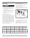
3. After the electrical wiring test/checklist is completed (end
of this chapter), replace the voltage select access panel.
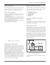
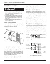
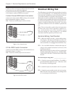
Fig 4-2 Input Voltage Jumper
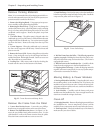
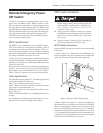
Input Wiring Procedure
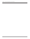
1. Refer to figure 4-3. Locate the input wiring entry and
input wiring inspection panels.
2. Remove the four screws securing the panels to the frame.
Remove only the screws indicated in the illustration. Place
the screws and panels to one side.
Fig 4-3 Removal of Input Hardwiring Panels
2. Pull the three input wires through conduit, leaving about
20” of wiring extending from the end. Install a flexible metal
conduit connector to the end of the conduit. Using appro-
priate tools, remove the knockout in the entry panel. Feed
the wires through the entry panel, and attach the flexible metal
conduit connector to the panel. Strip 1/2” of insulation from
the end of each of the incoming wires.
3. Feed wire into the entry compartment through the wiring
pathway hole between the input wiring entry compartment
and the input wiring compartment. See figure 4-4 for the
input wiring pathway.
Chapter 4 - Electrical Requirements and Procedures
4-3
240V
208V