


Installation Test
The following test procedure is intended to ensure that the
MIM, RIM and the power and battery modules have been
correctly installed. It will verify that the Symmetra
TM
is re-
sponding correctly and is ready to deliver power to the load
equipment. It is intended that the installer of the Symmetra
TM
system will perform this test.
Before this test can be conducted, the main intelligence module
(MIM), the PowerView display, at least one power module
and at least one battery module all must be properly installed.
Installation procedures are provided earlier in this chapter.
Note: This test is intended to verify the correct setup and instal-
lation of the Symmetra
TM
system. It is not intended to explain
it’s usage. In this procedure, you will be instructed to ignore
PowerView messages, etc. Refer to chapters 6 & 7 for detailed
information about the operation of Symmetra
TM
.
Installation Test/Checklist
q 1. Make sure all three switches - system enable, mainte-
nance bypass, and input circuit breaker are in the off or standby
position. Make sure all load equipment is either turned off, or
is unplugged from Symmetra
TM
.
Note: Load equipment can be left connected during this test
procedure, however power will be switched on and off to the load
equipment. Therefore, it is recommended that load equipment
be switched to the “off” position, until the completion of this
test.
q 2. Switch both the input circuit breaker and the system
enable switch to the “on” position. Symmetra
TM
will power up
internally, but will not deliver output voltage. The PowerView
will display text. Depending on the configuration of the
Symmetra
TM
, one or more messages such as “Number of Bat-
tery Modules has changed” may appear. Press the ESC navi-
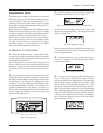
gation key until the startup screen appears. See figure 5-14.
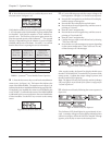
Verify that the input voltage is 208V or 240V nominal, that the
output voltage reads “000Vout,” and that all four of the
PowerView LED lights are off.
Fig 5-14 Startup Screen
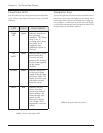
q 3. From the startup screen, press the ESC navigation key
to display the top level menu screen. See figure 5-15.
Fig 5-15 Top Level Menu & The Enter Navigation Key
Press the down arrow navigation key to select “Status,” and
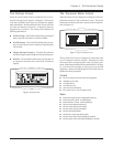
then press the enter navigation key. The voltage status screen
appears. See figure 5-16.
Fig 5-16 Voltage Status Screen
Read the voltge status screen to verify that input voltage (Vin)
is nominally either 208V or 240V. Verify that output voltage
(Vout) is approximately 0V.
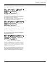
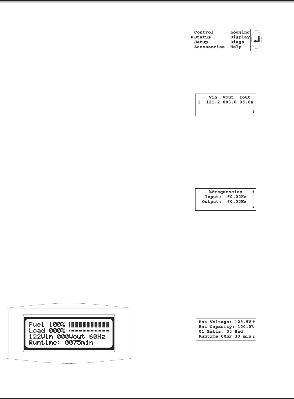
q 4. Press the down arrow key to scroll to the frequency
status screen. See figure 5-17. Verfiy that the input frequency
is approximately 60 Hz.
Fig 5-17 Frequency Status Screen
q 5. Press the down arrow key to scroll to the battery status
screen. See figure 5-18. Verfiy that the number of battery
modules reported (01 in the example below) is the same as the
actual number of battery modules that are installed. Verify
that the number of “bad” modules reported is zero. Verify
that there is a minimum of 90V of battery voltage reported.
Note: The reported battery voltage will vary from approximately
90V to 148V, depending on the state of the charge. If the reported
voltage is less than 90V, allow the battery modules to recharge.
(Leave the system enable switch and the input circuit breaker in
the “on” position, and allow the Power Array to remain idle for
approximately one half hour.)
Fig 5-18 Battery Status Screen
5-7
Chapter 5 - System Setup