


P
R
E
L
I
M
I
N
A
R
Y
T
E
C
H
N
I
C
A
L
D
A
T
A
P
R
E
L
I
M
I
N
A
R
Y
T
E
C
H
N
I
C
A
L
D
A
T
A
This information applies to a product under development. Its characteristics and specifications are subject to change with-
out notice. Analog Devices assumes no obligation regarding future manufacturing unless otherwise agreed to in writing.
19REV. PrA
For current information contact Analog Devices at (781) 461-3881
ADSP-2192October 2000
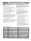
USB DSP Memory Buffer Size Register
Indicates the size of the DSP memory buffer assigned to this
endpoint.
• SZ[15:0] = Memory Buffer Size
USB DSP Memory Buffer RD Pointer Offset Register
The offset from the base address for the read pointer of the
memory buffer assigned to this endpoint.
• RD[15:0] = Memory Buffer RD Offset
USB DSP Memory Buffer WR Pointer Offset Register
The offset from the base address for the write pointer of the
memory buffer assigned to this endpoint.
• WR[15:0] = Memory Buffer WR Offset
USB Descriptor Vendor ID
The Vendor ID returned in the GET DEVICE DESCRIP-
TOR command is contained in this register. The DSP can
change the Vendor ID by writing to this register during the
Serial EEPROM initialization. The default Vendor ID is
0x0456, which corresponds to Analog Devices, Inc.
• V[15:0] = Vendor ID (default = 0x0456)
USB Descriptor Product ID
The Product ID returned in the GET DEVICE DESCRIP-
TOR command is contained in this register. The DSP can
change the Product ID by writing to this register during the
Serial EEPROM initialization. The default Product ID is
0x2192.
• P[15:0] = Product ID (default = 0x2192)
USB Descriptor Release Number
The Release Number returned in the GET DEVICE
DESCRIPTOR command is contained in this register. The
DSP can change the Release Number by writing to this reg-
ister during the Serial EEPROM initialization. The default
Release Number is 0x0100, which corresponds to
Version 01.00.
• R[15:0] = Release Number (default = 0x0100)
USB Descriptor Device Attributes
The device-specific attributes returned in the GET
DEVICE DESCRIPTOR command are contained in this
register. The DSP can change the attributes by writing to
this register during the Serial EEPROM initialization. The
default attributes are 0x80FA, which correspond to
bus-powered, no remote wake-up, and
max power = 500mA.
• SP: 1=self-powered, 0=bus-powered (default = 0)
• RW: 1=have remote wake-up capability, 0=no remote
wake-up capability (default = 0)
• C[7:0] = power consumption from bus, expressed in
2mA units (default = 0xFA 500mA)
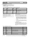
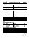
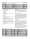
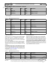
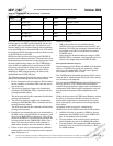
USB DSP MCU Register Definitions
MCU registers are defined in four memory spaces that are
grouped by the following address ranges:
• 0x0XXX—This address range defines general purpose
USB status and control registers
• 0x1XXX—This address range defines registers that are
specific to endpoint setup and control
• 0x2XXX—This address range defines the registers
used for REGIO accesses to the DSP register space
• 0x3XXX—This address range defines the MCU pro-
gram memory write address space
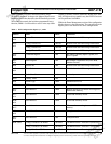
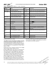
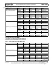
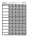
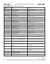
Table 12. USB MCU Register Definitions
Address Name Comments
0x0000- 0x0007 USB SETUP Token Cmd 8 bytes total
0x0008- 0x000F USB SETUP Token Data 8 bytes total
0x0010- 0x0011 USB SETUP Counter 16 bit counter
0x0012- 0x0013 USB Control Miscellaneous control including re-attach
0x0014- 0x0015 USB Address/Endpoint Address of device/active endpoint
0x0016- 0x0017 USB Frame Number Current frame number
0x0030- 0x0031 USB Serial EEPROM Mailbox 1 Defined by ADI
0x0032- 0x0033 USB Serial EEPROM Mailbox 2 Defined by ADI
0x0034- 0x0035 USB Serial EEPROM Mailbox 3 Defined by ADI