


Measurement Considerations Using the Power Sensor
3-14 MA24106A UG
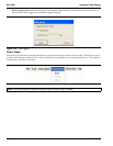
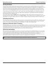
Error States
This section details some of the error messages that may appear on the application screen. In most cases, the
error condition can be easily corrected. The status LED will light yellow when an error state occurs. If not, note
the error message and contact an Anritsu Service Center.
3-9 Measurement Considerations
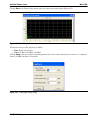
Time Varying Signals
Case 1: Modulated signals with pulse or pattern repetition times ≤ 1ms (PRF ≥ 1KHz)
If you obtain a steady power reading of a modulated signal (no significant fluctuations of the displayed power)
with no averaging, then it is likely that the pulse or pattern repetition rate is greater than 1 KHz. In this case,
most of the averaging of the envelope power is performed in the front end of the sensor (before being digitized).
When this is the case, the MA24106A will provide an accurate indication of the average power with no special
considerations.
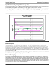
Case 2: Modulated signals with pulse or pattern repetition times between 1 ms and 50 ms
(100Hz <PRF <1KHz)
In this case, the signal is varying too slowly to be averaged in the front end of the sensor, so averaging must be
performed after digitalization by increasing the averaging number in the power meter application (or
calculating the average of several measurements if controlling the sensor over the bus). A large amount of
averaging must be used for some pulse/pattern repetition frequencies to get a steady reading. If Low Aperture
Time (LAT) mode is selected, the maximum recommended pulse repetition time is about 10 ms. If High
Aperture Time (HAT) mode is selected, signals with pulse repetition periods as long as 50 ms can usually be
measured.
Case 3: Modulated signals with pulse or pattern repetition times greater than 50 ms
In this case, it can be difficult to get an accurate average power reading even by averaging many readings. The
sample rate of the sensor and the pulse repetition rate of the signal may be close enough that they can “beat”
together resulting in low frequency modulation of the power indication. If averages are not calculated over
many of these beats, or an integer number of beats, errors can result. This is not unique to the MA24106A and
can be an issue with any power sensor/meter and any sampled data system.
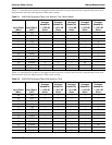
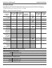
Table 3-3. Error Messages
Message Description Resolution
Zero invalid as temperature
changed by more than
10 Degrees C
The sensor’s ambient temperature has changed
by more than 10 ºC since the last zero
operation.
Perform the zero operation again.
Temperature out of
operating range
Operating range of the sensor is 0 ºC to 55 ºC. Re-examine the ambient
conditions.
Sensor zero failed This message box appears if the zero operation
is unsuccessful. The reason could be the
presence of RF power at the input of the sensor.
Turn off the RF input to the sensor
or disconnect the sensor from the
RF source and try the zero
operation again.
ZERO_ERROR This message appears on the application
screen if the zero operation is unsuccessful. The
reason could be the presence of RF power at
the input of the sensor.
Turn off the RF input to the sensor
or disconnect the sensor from the
RF source and try the zero
operation again.
ADC_TEMP_OVERRNGE This message appears on the application
screen if the sensor is being operated in
extremely high temperatures and has
overheated.
Remove the sensor from the USB
connection and allow to cool to
the operating range of the sensor:
0 ºC to 55 ºC