


Calibration Factor Test Sensor Operational Tests
5-4 MA24106A UG
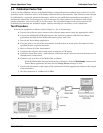
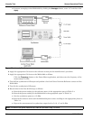
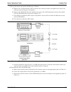
2. Connect the reference sensor to the synthesizer with the appropriate adapter and attenuator in-line (see
Figure 5-1).
3. Apply the appropriate Cal factor to the reference sensor per the manufacturer’s instruction.
4. Record the power indicated by the reference meter in the appropriate space in Table 5-3.
5. Disconnect the reference sensor from the synthesizer output and connect the MA24106A power sensor
with the appropriate adapter and attenuator in-line (see Figure 5-1).
6. Apply the appropriate Cal factor to the MA24106A as follows:
Press the Frequency button on the Power Meter application, and then enter the frequency of the
measurement in GHz.
7. Record the power indicated by the MA24106A in the appropriate space in Table 5-3.
8. Set the synthesizer frequency to the next frequency in Table 5-3.
9. Repeat steps 2 through 8 until all of the frequencies in Table 5-3 have been measured.
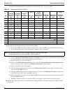
10. For each row in Table 5-3, calculate the absolute value of the difference between the recorded Reference
power measurement and the recorded MA24106A measurement, and record the result in the appropriate
space in Table 5-3.
11. For each frequency, compare the power difference to the maximum allowed difference specified in
Table 5-3. If the difference is higher than the maximum allowed difference, contact Anritsu customer
service.
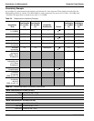
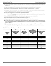
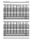
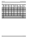
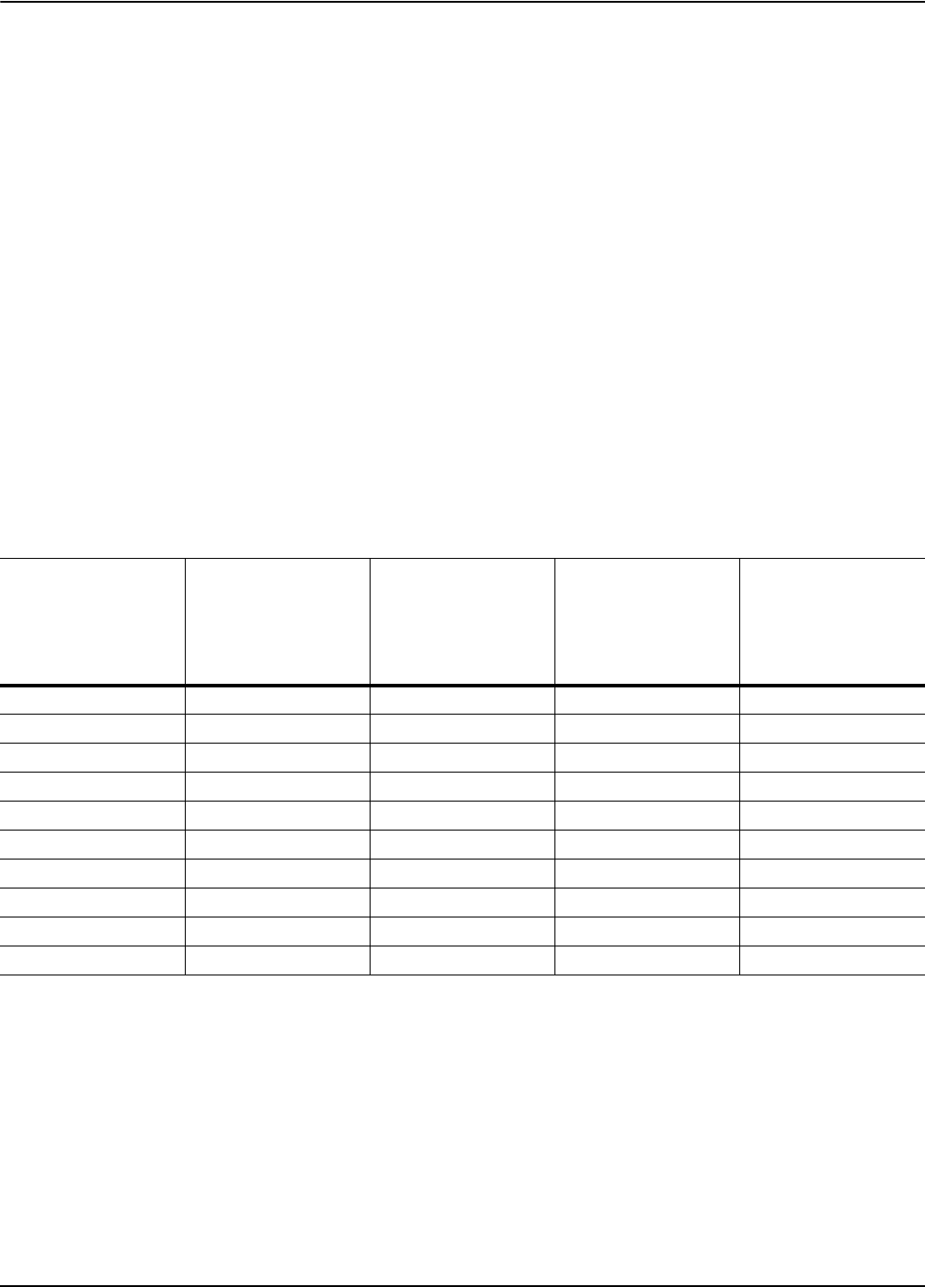
Table 5-3. Calfactor Test Measurement Results
Frequency
(GHz)
A
Reference Power
Measurement
(dBm)
B
MA24106A
Measurement
(dBm)
|A-B|
Absolute Value of
Difference in Power
Measurements
(dB)
Maximum Allowed
Difference
(dB)
0.05 0.26
0.1 0.26
0.3 0.26
0.5 0.26
1.0 0.26
2.0 0.31
3.0 0.31
4.0 0.31
5.0 0.33
6.0 0.33