


Page 10 - 6739380EN/JC
I
+–
!
!
O
2
beep...beep...
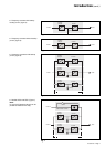
This signal warns the user of the
imminent end of battery power. On the
device itself, the buzzer beeps
increasingly rapidly and loudly.
Battery power stops when the voltage
supplied by the battery reaches the
voltage minimum (340V). This results in
inverter shutdown and transfer of the
load without interruption to Mains 2.
The red "load not protected" light 2 on
the control panel is on.
Battery time
The available battery time during a
Mains 1 outage depends on the:
◗ rated capacity of the battery;
◗ power consumed by the load;
◗ temperature of the battery;
◗ age of the battery.
The specified battery time corresponds
to a minimum duration at full rated load.
The actual backup time can therefore
be greater if the system operates below
its full rated load during the Mains 1
outage. Operation on battery power can
be extended beyond the specified time
by reducing the load power
consumption (by disconnecting non-
critical loads).
A "low battery shutdown" warning
signal is sent via volt-free changeover
contacts for remote control devices
when the battery voltage reaches a
level slightly above the minimum level.
If Mains 2 also fails, the load is no
longer supplied. Normally, the inverter
shuts down when the time on the
battery power exceeds three times the
specified backup time.
Note:
As an optional function (battery time
estimator), the "low battery shutdown"
warning signal can be sent with an
adjustable time delay prior to the
effective end of battery power.
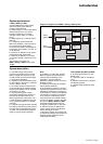
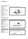
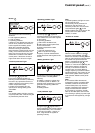
Fig. 13
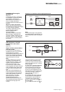
Battery charge cycle
Operation with Mains 1 restored
(figure 13)
When Mains 1 power is restored or its
voltage returns to within specified
tolerances, the system automatically
returns to its normal operating mode
described above (on the condition it did
not reach the end of battery power).
If the end of battery power was reached
(with the resulting inverter shutdown),
the RC restarts automatically, but the
inverter must be restarted manually,
either locally or remotely in systems
equipped with a remote-control unit.
The rectifier-charger recharges the
battery which was discharged during
the Mains outage.
Note:
In frequency converters without battery
power, the return of Mains 1 power
results in the automatic restart of the
RC and the inverter.
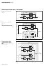
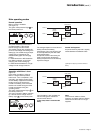
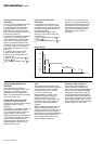
The battery charge cycle takes place in
two steps (see figure 14):
◗ step 1: the battery is recharged at a
constant current limited to 0.1C10
(i.e. 1/10th of the battery capacity
specified for a 10 hour discharge).
The DC voltage increases with the
battery charge until the charge level is
reached;
◗ step 2: the battery is recharged at
constant voltage equal to the charge
level (maximum value 463V).
The charging current gradually
decreases until reaching a specified
low value (floating current).
For vented lead-acid batteries, the
rectifier-charger supplies the charging
voltage for 0 to 255 hours (parameter
defined by the after-sales support
department) and then the floating
voltage. For sealed lead-acid batteries,
Fig. 14
the charging and floating voltages are
the same.
Note:
If the Mains 1 failure is shorter than 0 to
255 seconds (parameter defined by the
after-sales support department), the
charger does not initiate a complete
charge cycle but automatically supplies
the floating voltage.
mains 1
rectifier-
charger
battery
inverter
load
static switch
mains 2
U/I
current
limiting
0.1 C10
constant voltage
decreasing current
voltage
current
t
U charge/floating
(sealed batteries)
U "floating"
(vented batteries)
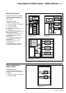
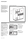
Introduction (cont.)