


6739380EN/JC - Page 19
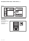
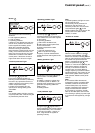
Light A - emergency shutdown
This red light signals that the remote
"emergency shutdown" button was
pressed (external information received
and stored in memory).
Light B - rectifier-charger on
This green light indicates that the
rectifier-charger is on.
Light C - rectifier-charger fault
This red light is an alarm stored in
memory signaling a rectifier-charger
fault. It can signify one or several of the
following faults:
◗ input switch Q1 open;
◗ RC input protection fuse (FU1-2-3)
blown;
◗ RC internal over-temperature;
◗ battery charge over-current;
◗ battery over-voltage;
◗ RC electronic control board faulty,
not calibrated or not personalized;
◗ power supply board fault.
Light D - Mains 1 outside tolerances
This yellow light signals that the
Mains 1 voltage and/or frequency
characteristics are outside tolerances.
Light E - battery room ventilation
fault and/or harmonics filter
temperature outside tolerances
This yellow light is an alarm stored in
memory signaling a battery room
ventilation fault (external information
that must be supplied from the room).
If the installation includes a harmonics
filter, this light will also signal an
overtemperature of the filter’s inductor
(information supplied).
Light F - battery temperature outside
tolerances
This yellow light signals that the battery
temperature is outside tolerances
(external information supplied by
special board ("Temperature Monitor"
option).
Light G - battery charging
This yellow light signals that the battery
is being recharged (vented batteries
only). This light is deactivated in
systems with sealed lead-acid
batteries.
Light H - inverter fault
This red light is an alarm stored in
memory signaling an inverter fault. It
can signify one or several of the
following faults:
◗ inverter shutdown due to inverter
output voltage outside tolerances;
◗ inverter output protection fuse (FU5-
6-7) blown;
◗ inverter stack subassembly
protection fuse blown (parallel
systems);
◗ inverter leg fault;
◗ inverter output transformer over-
temperature;
◗ inverter leg over-temperature;
◗ phase or output voltage fault (parallel
systems only);
◗ internal clock fault;
◗ inverter control board faulty, not
calibrated or not personalized;
◗ power supply board fault.
Light I - battery discharged
This yellow light signals that the battery
has reached its minimum voltage level,
resulting in inverter shutdown.
Light J - inverter desynchronized
with Mains 2
This light signals that the inverter
output frequency has been voluntarily
desynchronized with that of Mains 2.
Light K - transfer to inverter function
fault
This red light is an alarm stored in
memory signaling a fault in the systems
for load transfer from Mains 2 to the
inverter. It can signify one or several of
the following faults:
◗ inverter output switch K3N fault;
◗ parallel-connection relay fault
(parallel systems only);
◗ static switch internal over-
temperature;
◗ static switch ventilation fault;
◗ static switch power supply fault;
◗ transfer function control board fault;
◗ inverter control board not calibrated
or not personalized;
◗ power supply board fault.
Light L - overload
This yellow light is an alarm signaling
one or several of the following faults:
◗ inverter stack current more than 5%
above rated current;
◗ inverter output current more than 5%
above rated current;
◗ Mains 2 line current more than 5%
above rated current;
◗ inverter shutdown due to current
limiting of output current.
Light M - Mains 2 outside tolerances
This yellow light signals that the
Mains 2 voltage or frequency
characteristics are outside tolerances.
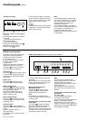
Light
N - maintenance position
This yellow light signals that devices
QF1, Q4S, Q5N and Q3BP are set to
the maintenance configuration. The
UPS system is not available for load
protection.
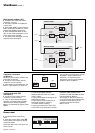
Test connector
This 9-pin connector is reserved for
after-sales support technicians.
It is used for connection to a
microcomputer for:
◗ system calibration;
◗ personalization;
◗ computer-aided diagnostics.
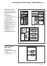
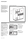
Control panel (cont.)