


6739380EN/JC - Page 5
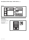
Introduction
System performance
System description
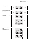
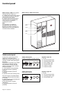
Note:
◗ the Mains 1 normal input and the
Mains 2 bypass input have different
functions and, depending on the
installation, may be protected
differently upstream and/or come from
different sources;
◗ frequency converters are available
without backup batteries;
◗ the emergency bypass line and the
maintenance bypass line do not exist in
installations where the load frequency
and the Mains 2 frequency are different
(for example in frequency converters);
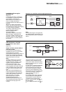
◗ for reasons of redundancy and/or
increased power, the rectifier-charger,
inverter and battery modules (the UPS,
part A in the MGE
TM
Galaxy
TM
6000
schematic diagram above) may be
arranged in parallel lines. In this case,
an isolation function is added to the
output of each UPS for maintenance
without disrupting the load.
In this type of system, the components
of part B in the diagram are located in a
separate cubicle referred to as the
"Static Switch Cubicle".
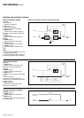
The system may also include:
◗ an isolating transformer on the
Mains 2 line;
◗ a harmonics filter on the Mains 1
input;
◗ different remote control, indication
and display systems;
◗ a double bridge rectifier-charger
module.
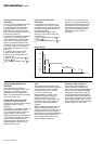
A MGE
TM
Galaxy
TM
6000
uninterruptible power supply (UPS)
delivers 3-phase power with the
following characteristics:
◗ stable voltage (+/-0.5% under steady
state conditions and +/-5% under
transient conditions for load step
changes of 25 to 100% or of 100 to
25%);
◗ stable frequency (+/-0.05Hz without
Mains 2);
◗ or frequency synchronized with
Mains 2 to 50/60Hz +/-2Hz (value may
be configured in 0.25 HZ steps);
◗ free of micro-breaks and outages for
the duration of the battery time (10, 15
or 30 minutes);
◗ less than 4% distortion in all system
configurations with linear loads;
◗ less than 5% distortion for a 100%
non-linear load with a peak factor of up
to 3.5.
The acoustic noise level of a
MGE
TM
Galaxy
TM
6000 UPS is under
70dBA.
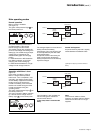
◗ a rectifier-charger (RC) module
converts 3-phase AC power from the
Mains 1 supply into DC power for the
normal inverter input and float charges
or recharges the batteries;
◗ a battery unit provides backup power
for the inverter in the event of a voltage
drop or a Mains 1 failure;
◗ an inverter module converts the DC
power supplied by the rectifier-charger
module or the battery unit into 3-phase
AC power for the load;
◗ an emergency bypass module
ensures the instantaneous transfer of
the load via the static switch to the
Mains 2 bypass line in the event of an
inverter shutdown (initiated by the user
or by a protective device) or a sudden
overload;
◗ a maintenance bypass which isolates
the UPS for maintenance and transfers
the load without interrupting the supply
of power. The maintenance bypass is
made up of three manual switches.
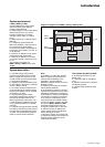
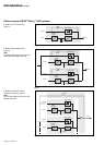
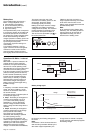
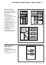
Single-line diagram of the MGE
TM
Galaxy
TM
6000 system
maintenance
bypass
emergency
bypass
DC/AC
conversion
isolation
isolation
and
protection
AC/DC
conversion
isolation and
protection
battery
load
mains 1
(normal input)
mains 2
(bypass input)
A
B
isolation
and
protection