


6739380EN/JC - Page 21
I
+–
!
!
O
6
I
+–
!
!
O
2
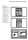
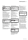
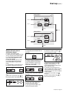
Modular UPS with external
maintenance bypass
Proceed in the following order:
◗ check that all lines supplying the load
are off or that the load is disconnected;
◗ in the maintenance bypass cubicle,
open output switch Q5N, then close
bypass switch Q3BP;
◗ close the upstream switch (on the
low-voltage switchboard) supplying
power to the Mains 1 inputs on the
UPSs;
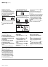
◗ close the Mains 1 input switch Q1 on
the UPSs to supply them with power:
◗◗ the rectifier/chargers automatically
start;
◗◗ red "load not protected" light 2 on
the control panels of the UPSs goes on:
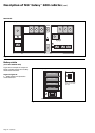
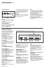
◗ close battery circuit breaker QF1 on
the UPSs:
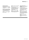
◗ close the upstream switches (on the
low-voltage switchboard) supplying
power to the Mains 2 inputs on the
UPSs, then close the Mains 2 input
switch Q4S on the UPSs:
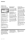
◗ close inverter output switch Q5N on
the UPSs:
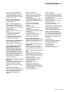
◗ close output switch Q5N in the
maintenance bypass cubicle;
◗ open bypass switch Q3BP in the
maintenance bypass cubicle;
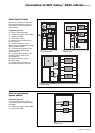
◗ press the "inverter on" button 6 on
the control panel of a UPS:
◗◗ green "load protected" light 5
flashes for three seconds,
◗◗ the inverter starts and waits for the
start of the other units;
◗ proceed in the same manner for
each unit. When the number of running
units is sufficient, the inverter output
switches close and the load is supplied
by the inverters:
◗◗ red "load not protected" light 2
goes off,
◗◗ green "load protected" light 5 on
the control panel goes on.
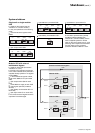
Q1 Q4S Q5N
OFF
ON
(0)
(I)
OFF
(0)
OFF
(0)
QF1
OFF
ON
(0)
(I)
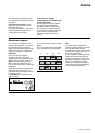
Q1 Q4S Q5N
OFF
ON
(0)
(I)
ON
(I)
OFF
(0)
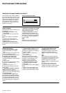
Q1 Q4S Q5N
OFF
ON
(0)
(I)
ON
(I)
ON
(I)
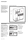
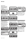
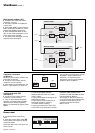
Start-up (cont.)
Q1
Q5N
QF1
Q3BP
Q4S
Q1
Q5N
QF1
Q3BP
Q4S
Galaxy UPS 2
load
battery
inverter
mains 1
rectifier-
charger
static switch
mains 2
Galaxy UPS 1
battery
inverter
mains 1
rectifier-
charger
static switch
mains 2