


6739380EN/JC - Page 29
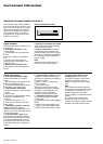
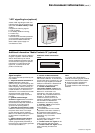
"LED" signalling box (optional)
Additional information "Media Contacts 15" (optional)
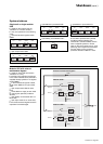
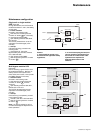
Additional remote transmission
board
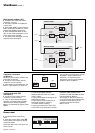
◗ "transfer to Mains 2 disabled"
signal blocks transfer of the load from
the inverter to Mains 2. In the event the
inverter shuts down (overload, etc.), the
load is no longer supplied (for modular
UPSs, this information is disabled and
transferred to an auxiliary output);
◗ "transfer to Mains 2 with
interruption disabled" signal blocks
transfer of the load from the inverter to
Mains 2 if it would result in an
interruption in the supply of power to
the load. Only no-break transfers are
allowed, i.e. transfer to Mains 2
conditions must be correct or the
transfer is disabled (for modular UPSs,
this information is disabled and
transferred to an auxiliary output);
◗ "auxiliary" signal can be used to
provoke (depending on
personalization):
◗◗ a forced shutdown of the inverter
(regardless of the status of Mains 2),
◗◗ a protected inverter shutdown
(transfer of the load to Mains 2 without
interruption only if it is within
tolerances),
◗◗ modification of the inverter output
frequency (50Hz or 60Hz);
◗ "remote inverter on" signal can be
used to remotely start the inverter;
◗ "remote inverter off" signal can be
used to remotely shut down the
inverter.
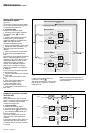
Signal reception
The signals should be provided by volt-
free contacts.
◗ "desynchronization with Mains 2"
signal inhibits the inverter from
synchronizing its output frequency with
that of Mains 2. The inverter supplies a
stable frequency and the load may no
longer be correctly transferred from the
inverter to Mains 2. In the event of a
malfunction or an overload, the transfer
will take place with a 0.8 second
interruption in the supply of power to
the load;
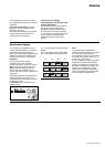
◗ "gradual rectifier/charger
shutdown" signal makes the rectifier/
charger shut down progressively to
avoid excessive step load variations in
the event of a low output engine
generator set replacing Mains 1;
◗ "generator current limiting" signal
makes the rectifier/charger current limit
the power drawn when a low output
engine generator set has replaced
Mains 1. The additional power required
for the inverter is supplied by the
battery;
◗ "battery charge current limiting"
signal reduces the battery charge
current (programmable parameter) in
the event a low output engine generator
set has replaced Mains 1;
Note:
In a system with a Static Switch
Cubicle, the following signals must be
directed to the Static Switch Cubicle:
◗◗ desynchronization with Mains 2,
◗◗ transfer to Mains 2 disabled,
◗◗ transfer to Mains 2 with interruption
disabled.
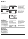
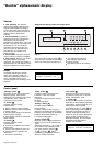
A basic "LED" signalling box with four
indication lights may be supplied as an
option with the MGE
TM
Galaxy
TM
6000
system.
It supplies the following signals:
◗ load on battery;
◗ low battery shutdown warning;
◗ inverter stop;
◗ general alarm.
It connects to the terminals presented
on the preceding page and draws its
power from the external 220V AC,
50Hz or 60Hz power supply not
connected to a UPS.
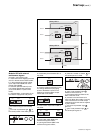
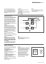
An additional board may be installed in
all types of systems. Terminals XR5 to
XR9 on the board may be used to
receive additional information from the
environment and supply more precise
information on system status (see
figures 18, 19, 20 and 22 for the
position of the board).
test
Fonctionne
men
t
sur batt
erie
P
réa
larm
e fin
d'a
uto
.ba
tt
erie
On
duleur à l'ar
rêt
Alarme
globa
le
XR5 XR6 XR7XR9XR8
Environment information (cont.)