


6739380EN/JC - Page 15
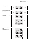
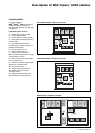
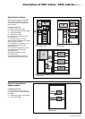
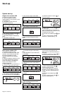
Static Switch Cubicle
front view, doors open, protective covers removed
Fig. 23
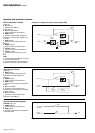
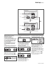
Static Switch Cubicles are rated 500,
800, 1200 and 2000 kVA. Figure 23
presents the layout of components in
these cubicles.
Legend for figure 23:
2-Mains 2 input switch Q4S,
3-maintenance bypass switch Q3BP,
4-output switch Q5N,
5-static switch module,
6-electronic control boards for the
backup function,
7-protection fuses FU1 for the
Mains 2 resistance/capacitance voltage
surge protection network,
8-fuse switch Q1 (protection of the
control electronics power supply
against Mains 1),
9-fuse switch Q2 (protection of the
control electronics power supply
against Mains 2),
10- "Media Contacts 9" remote
indications board,
11- additional "Media Contacts 15"
remote indications board (optional).
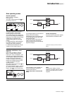
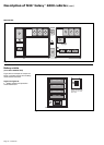
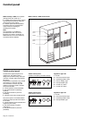
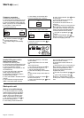
Fig. 24
External maintenance
bypass cubicle
Legend for figure 24:
1-connection of auxiliary wires to
indicate the positions of switches Q5N
and Q3BP,
2-maintenance bypass switch Q3BP,
3-output switch Q5N.
8
5
6
97
2
3
4
10
11
5
6
5
2
3
4
897
11 10
4
3
2
7
6
89
11
10
5
500 or 800kVA cubicle
1200kVA cubicle
2000kVA cubicle
Description of MGE
TM
Galaxy
TM
6000 cubicles (cont.)
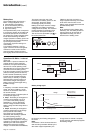
1200kVA cubicle
2
3
1