


6739380EN/JC - Page 25
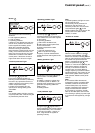
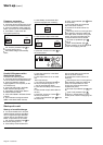
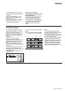
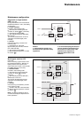
System shutdown
◗◗ open Mains 2 input switch Q4S:
◗◗ open battery circuit breaker QF1:
◗◗ open Mains 1 input switch Q1:
◗ the UPS is powered down (except
the Mains cables upstream from
switches Q1, Q4S and Q3BP) and the
load is supplied by Mains 2. All the
lights on the control panel are off. A full
powering down requires load shutdown
and the opening of the upstream
protection devices on Mains 1 and 2.
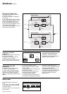
Single-unit or single modular
UPS
◗ shutdown the inverter (see the
"shutdown of a module" section);
◗ carry out operations in the following
order:
◗◗ close maintenance bypass switch
Q3BP:
◗◗ open output switch Q5N:
Q1 Q4S Q3BP Q5N
OFF
ON
(0)
(I)
ON
(I)
ON
(I)
ON
(I)
Q1 Q4S Q3BP Q5N
OFF
ON
(0)
(I)
ON
(I)
ON
(I)
ON
(I)
Q1 Q4S Q3BP Q5N
ON
OFF
(I)
(0)
ON
(I)
ON
(I)
OFF
(0)
QF1
OFF
ON
(0)
(I)
Q1 Q4S Q3BP Q5N
ON
OFF
(I)
(0)
OFF
(0)
ON
(I)
OFF
(0)
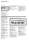
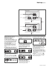
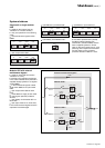
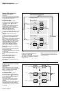
Modular UPS with external
maintenance bypass
◗ shutdown each UPS (see section
"shutdown of a unit");
◗ transfer to the maintenance bypass
in the order indicated below (the load is
supplied directly by Mains 2 via bypass
switch Q3BP):
◗◗ in the maintenance bypass cubicle,
close switch Q3BP, then open switch
Q5N;
◗◗ open output switch Q5N for each
UPS;
◗◗ cut the Mains 2 supply to each UPS
by opening the upstream protection
devices;
◗◗ open battery circuit breaker QF1 on
each UPS;
◗◗ open input switch Q1 on each UPS;
◗ the UPSs are de-energised once the
capacitors have discharged.
Q1
Q5N
QF1
Q3BP
Q4S
Q1
Q5N
QF1
Q4S
Modular UPS 2
Modular UPS 1
Q5N
External maintenance bypass
load
battery
inverter
mains 1
rectifier-
charger
static switch
mains 2
battery
inverter
mains 1
rectifier-
charger
static switch
mains 2
Shutdown (cont.)