


Magnum VS –48 Vdc User’s Manual Page 12
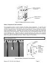
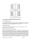
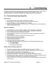
Figure 3.8-2 Top Shelf GMT Fuse Connections
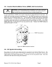
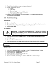
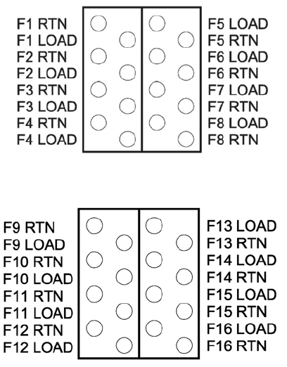
Figure 3.8-3 Bottom Shelf GMT Fuse Connections
3.9. Monitoring and Relay Output Connections
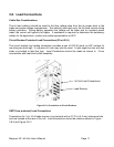
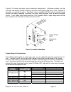
Front Panel DB9 Connection
The front panel DB-9 connector is used to hook up a standard RS-232 cable (such as APC part
number 0129-XX. A 0129-6 is included with this manual. ). This will allow local access through
a Terminal Emulation program such as HyperTerminal™ or Procomm.™
RJ45 Ethernet Connector
The management card has an RJ-45 connector to support a TCP/IP protocol over a 10/100
BaseT Ethernet Local Area Network (LAN).
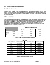
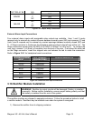
Major, Minor and Relay 1 Output Connections
There are three output relays available that provide outputs via Form “C” contacts. The output
relays are named Minor, Major and Out Relay 1. Various system alarm conditions can be
assigned to any of these three output relays. Most alarm conditions are shipped programmed to
Minor or Major Relay. Wago connectors are located on the backplane card mounted in the left
rear of the unit. Refer to the board layout in Figure 3.9-1 for Output Relay connections. The
Wago connectors accept wires 26 AWG to 20 AWG (0.129mm
2
to 0.518 mm
2
). To connect the
relay output, remove ¼ in (6mm) of insulation from the end of the wire. Push down the white tab
on the Wago connector, insert the stripped wire and release the tab to make the connection.
The relay contacts should only be used to switch resistive loads of 0.5 A or less at 60 V or less.