


Magnum VS –48 Vdc User’s Manual Page 3
AC
DC
Control
AC
DC
Control
AC
DC
Control
AC
DC
Control
AC
DC
Control
GND
L1 L2/N
GND
L1 L2/N
GND
L1 L2/N
GND
TRM15
1
2
3
4
5
6
7
8
ALM RTN
ALM RTN
ALM RTN
ALM RTN
1
2
3
4
5
6
7
8
9
1
2
3
4
MAJ NC
MAJ NO
MIN NC
MIN NO
USER NC
USER C
MIN C
MAJ C
USER NO
TMP
-BAT
+12 PWR
-PWR
+PWR
CONTROL BUS
Power Distribution Backplane
RESET
CONTROL BUS
CONTROL BUS
Energized
TX2 Relay
BATTERY
LVD
AC
DC
Control
AC
DC
Control
AC
DC
Control
AC
DC
Control
AC
DC
Control
GND
L1 L2/N
GND
L1 L2/N
GND
L1 L2/N
GND
TRM15
1
2
3
4
5
6
7
8
1
2
3
4
5
6
7
8
9
1
2
3
4
-PWR
+PWR
CONTROL BUS
Power Distribution Backplane
CONTROL BUS
Energized
TX2 Relay
BATTERY
LVD
Visual Alarm
Stud outputs:
Rear
Blank Panel
COVERED
COVERED
COVERED
MINOR
ALM IN_1
ALM IN_2
ALM IN_3
ALM IN_4
COMM
PORT
DB-9
PORT
2 Visual Alarms
(1 per group of 4)
DC OK
MAJOR
OUT RLY
USER
ALARM
INPUTS
ALARM
RELAY
OUTPUTS
BATTERY
TEMPERATURE
PROBE
Signals Cable
TOP SHELF
BOTTOM SHELF
8 outputs: Rear
GMT Load Distribution Module
( 0P1849 )
BATTERY
SHUNT
BATTERY
SHUNT
2 CB Load Distribution Module ( 0P1852 )
Microprocessor
Control Board
( 0P1838 )
WEB
SNMP Card
( AP9617 )
( 0P1839 )
( 0P1839 )
BATTERY (–)
BATTERY (+)
BATTERY (–)
BATTERY (+)
Visual Alarm
100 Amp System Only
Bus Bars
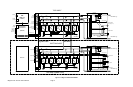
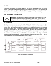
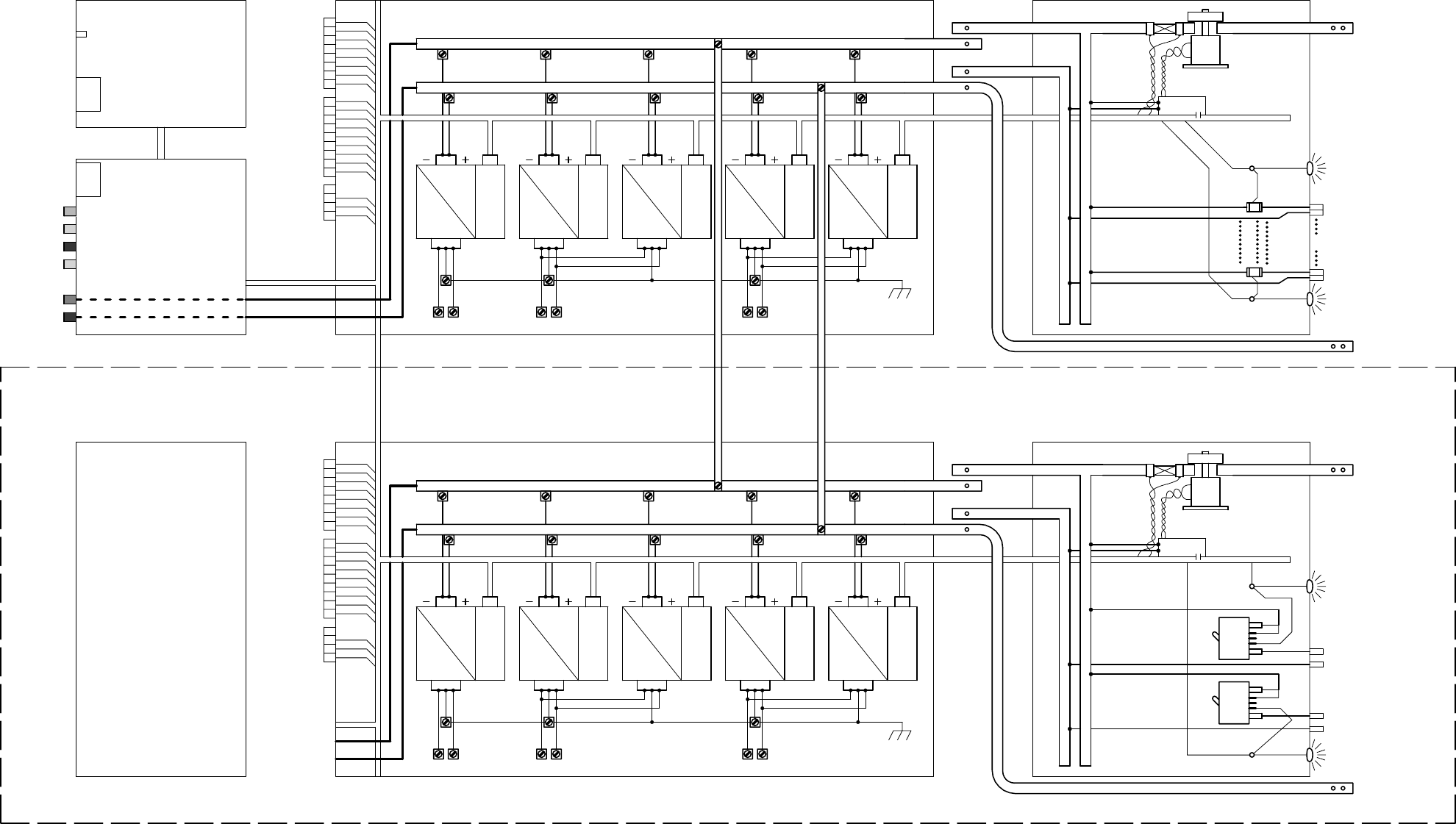
Figure 2.2-1 Magnum VS BLOCK DIAGRAM