


Magnum VS –48 Vdc User’s Manual Page 15
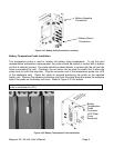
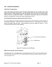
2) Slide the rectifier module into the shelf between the guides until it is fully seated.
3) Fasten the rectifier in place with the captive rectifier retaining screws.
Since all adjustments are made from the system controller, no rectifier adjustments are
necessary.
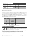
3.11. Controller Module Installation
CAUTION: The controller and the network management card have lithium
batteries. These batteries are not field serviceable.
• Danger of explosion if battery is replaced by an incorrect type.
• Dispose of used batteries according to the manufacturer’s instructions.
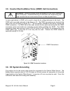
The controller is installed in the Magnum VS 50 in the right hand side of the power system. The
controller is installed in the Magnum VS 100 in the upper right hand side of the power system.
Insert the card taking care to follow the alignment guides all the way to the rear of the unit. The
connector on the rear will hot plug into the power system backplane.
To install the controller with display, first remove rectifier number 5, which is in the slot nearest
the controller. Insert the card taking care to follow the alignment guides all the way to the rear of
the unit. The connector on the rear will hot plug into the power system backplane. Removing
the rectifier will decrease the total output capacity of the power system.