


Magnum VS –48 Vdc User’s Manual Page 14
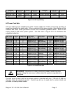
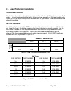
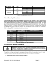
OUT RELAY #6 N/A
NO N/A
MINOR C N/A
NC N/A
NO N/A
MAJOR C N/A
NC N/A
Figure 3.9-3 Output Relay Connections
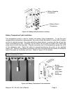
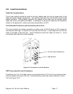
External Alarm Input Connections
Four external alarm inputs with assignable relay outputs are available. User 1 and 2 inputs
respond only to external dry contact closures between normally open (NO) and common (C) and
User 3 and 4 respond only to external dry contact openings between normally closed (NC) and
C. A Wago connector is located on the backplane card mounted in the left rear of the unit. The
Wago connectors accept wires 26 AWG to 20 AWG (0.129mm
2
to 0.518 mm
2
). To connect the
user input, remove ¼ in (6mm) of insulation from the end of the wire. Push down the white tab
on the Wago connector, insert the stripped wire and release the tab to make the connection.
Refer to Figure 3.9-1 for backplane board connections.
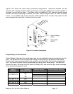
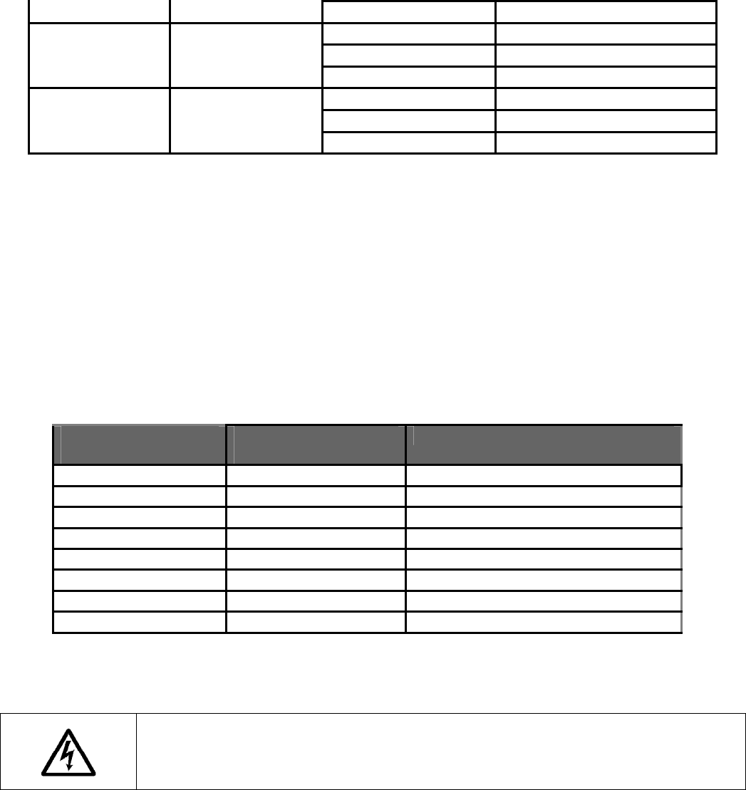
EXTERNAL ALARM
INPUT
J412 TERMINAL
DESIGNATIONS
USER ALARM NOTES
#1 NO USER1NO
#2 NO USER2NO
#3 NC USER3NC
#4 NC USER4NC
#1 C USER1C
#2 C USER2C
#3 C USER3C
#4 C USER4C
Figure 3.9-5 External User Input Connections
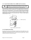
3.10. Rectifier Module Installation
WARNING: Rectifier dc output circuits will be damaged if battery is installed
incorrectly. Before rectifier installation, ensure proper battery polarity and that
the battery is isolated from the rest of the system
The rectifier modules are shipped in separate containers. Follow the procedure below to install
a rectifier module. Rectifiers may be installed even when the system is energized.
1) Remove the rectifier from its shipping container.