


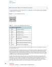

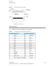
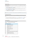
Signal namePin numberSignal namePin number
CSEL28IORDY, /DDMARDY, DSTROBE27
GROUND30/DMACK29
/IOCS1632INTRQ31
/PDIAG, /CBLID34/DA133
/DA236/DA035
/CS138/CS037
GROUND40/DASP39
+5V MOTOR42+5V LOGIC41
Reserved44GROUND43
/IOCS16 is not used; see Table 3-7 (page 36).
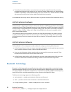
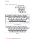
ATA Signal Descriptions
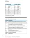
Table 3-7 (page 36) describes the signals on the ATA hard disk connector.
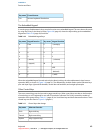
Table 3-7 Signals on the ATA hard disk connector
Signal descriptionSignal name
Device address; used by the computer to select one of the registers in the ATA drive. For
more information, see the descriptions of the CS0 and CS1 signals.
/DA(0–2)
Data bus; buffered from IOD(16–31) of the computer’s I/O bus. DD(0–15) are used to transfer
16-bit data to and from the drive buffer. DD(8–15) are used to transfer data to and from the
internal registers of the drive, with DD(0–7) driven high when writing.
DD(0–15)
The host checks this signal after power on or hardware reset to detect whether an
80-conductor cable is present.
/CBLID
Register select signal. It is asserted low to select the main task file registers. The task file
registers indicate the command, the sector address, and the sector count.
/CS0
Register select signal. It is asserted low to select the additional control and status registers
on the ATA drive.
/CS1
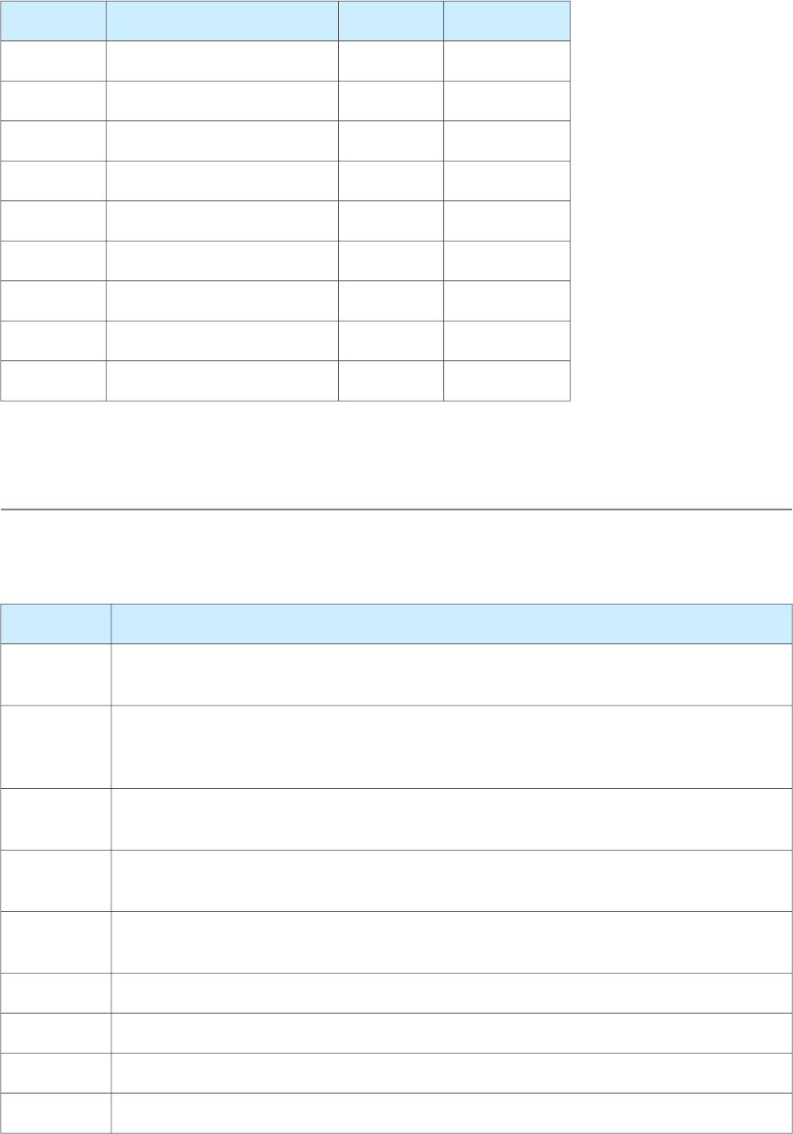
Cable select; not available on this computer (n.c.).CSEL
Device active or slave present; not available on this computer (n.c.)./DASP
Drive ready to receive Ultra DMA data./DDMARDY
I/O data read strobe./DIOR
36
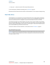
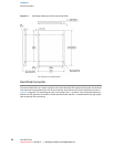
Hard Disk Drive
Legacy Document | 2003-03-01 | © 2003 Apple Computer, Inc. All Rights Reserved.
CHAPTER 3
Devices and Ports