


Figures and Tables
Chapter 1
Overview of PowerBook G4 17-inch 11
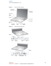
Figure 1-1 Front view of the computer 13
Figure 1-2 Side views showing I/O ports 13
Chapter 2
Architecture 17
Figure 2-1 Block diagram 17
Table 2-1 Buses supported by the Intrepid IC 19
Chapter 3
Devices and Ports 25
Figure 3-1 USB Type A port 25
Figure 3-2 6-pin FireWire connector 27
Figure 3-3 9-pin FireWire 800 connector 28
Figure 3-4 Maximum dimensions of the internal hard disk 34
Figure 3-5 Hard disk connector and location 35
Figure 3-6 Keyboard layout 39
Figure 3-7 Alternate operations of function and control keys 40
Figure 3-8 Embedded numeric keypad operation 41
Figure 3-9 DVI-I connector 47
Figure 3-10 S-video connector 48
Table 3-1 Pin assignments on the USB port 25
Table 3-2 Pin assignments on the 6-pin FireWire connector 27
Table 3-3 Signals on the 9-pin FireWire 800 connector 28
Table 3-4 Signals for 10Base-T and 100Base-T operation 29
Table 3-5 Signals for 1000Base-T operation 30
Table 3-6 Pin assignments on the ATA hard disk connector 35
Table 3-7 Signals on the ATA hard disk connector 36
Table 3-8 Media read and written by the SuperDrive 37
Table 3-9 The function keys as control buttons 42
Table 3-10 Embedded keypad keys 43
Table 3-11 Control keys that change 43
Table 3-12 Picture sizes on the flat-panel display 44
Table 3-13 Picture sizes on an analog monitor 45
Table 3-14 Picture sizes on a digital display 46
Table 3-15 Main signals on the DVI-I connector 47
Table 3-16 MicroCross signals on the DVI-I connector 47
Table 3-17 Pin assignments for the S-video output connector 48
Table 3-18 Picture sizes for S-video output 48
7
Legacy Document | 2003-03-01 | © 2003 Apple Computer, Inc. All Rights Reserved.