


ASUS P5LD2 DeluxeASUS P5LD2 Deluxe
ASUS P5LD2 DeluxeASUS P5LD2 Deluxe
ASUS P5LD2 Deluxe
2-312-31
2-312-31
2-31
11.11.
11.11.
11.
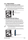
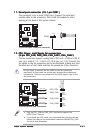
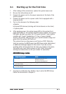
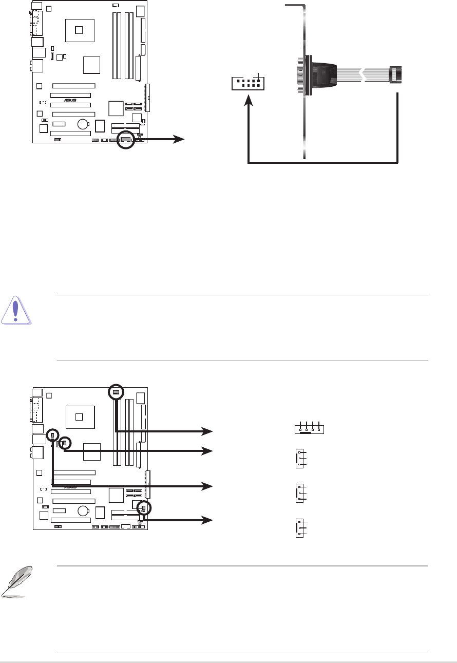
Serial port connector (10-1 pin COM1)Serial port connector (10-1 pin COM1)
Serial port connector (10-1 pin COM1)Serial port connector (10-1 pin COM1)
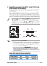
Serial port connector (10-1 pin COM1)
This connector is for a serial (COM) port. Connect the serial port
module cable to this connector, then install the module to a slot
opening at the back of the system chassis.
12.12.
12.12.
12.
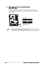
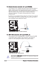
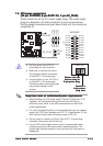
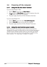
CPU, Power, and Chassis fan connectorsCPU, Power, and Chassis fan connectors
CPU, Power, and Chassis fan connectorsCPU, Power, and Chassis fan connectors
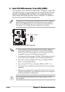
CPU, Power, and Chassis fan connectors
(4-pin CPU_FAN, PWR_FAN, CHA_FAN1, CHA_FAN2)(4-pin CPU_FAN, PWR_FAN, CHA_FAN1, CHA_FAN2)
(4-pin CPU_FAN, PWR_FAN, CHA_FAN1, CHA_FAN2)(4-pin CPU_FAN, PWR_FAN, CHA_FAN1, CHA_FAN2)
(4-pin CPU_FAN, PWR_FAN, CHA_FAN1, CHA_FAN2)
The fan connectors support cooling fans of 350 mA ~ 2000 mA (24 W
max.) or a total of 1 A ~ 3.48 A (41.76 W max.) at +12V. Connect the
fan cables to the fan connectors on the motherboard, making sure that
the black wire of each cable matches the ground pin of the connector.
• Only the CPU_FAN and CHA_FAN1 connectors support the
ASUS Q-Fan 2 feature.
• If you install two VGA cards, we recommend that you plug the rear
chassis fan cable to the motherboard connector labeled CHA_FAN1
for better heat dissipation.
Do not forget to connect the fan cables to the fan connectors.
Insufficient air flow inside the system may damage the motherboard
components. These are not jumpers! Do not place jumper caps on the
fan connectors!
P5LD2 DELUXE
®
P5LD2 DELUXE COM port connector
PIN 1
COM1
P5LD2 DELUXE
®
P5LD2 DELUXE Fan connectors
CPU_FAN
CHA_FAN2
PWR_FAN
CHA_FAN1
GND
Rotatio
n
+12V
GND
Rotatio
n
+12V
CPU_FAN
CHA_FAN2
PWR_FAN
CHA_FAN1
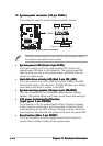
GND
Rotatio
n
+12V
GND
CPU FAN PWR
CPU FAN IN
CPU FAN PWM