


2-322-32
2-322-32
2-32
Chapter 2: Hardware informationChapter 2: Hardware information
Chapter 2: Hardware informationChapter 2: Hardware information
Chapter 2: Hardware information
14.14.
14.14.
14.
Chassis intrusion connector (4-1 pin CHASSIS)Chassis intrusion connector (4-1 pin CHASSIS)
Chassis intrusion connector (4-1 pin CHASSIS)Chassis intrusion connector (4-1 pin CHASSIS)
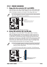
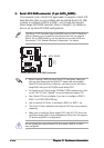
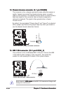
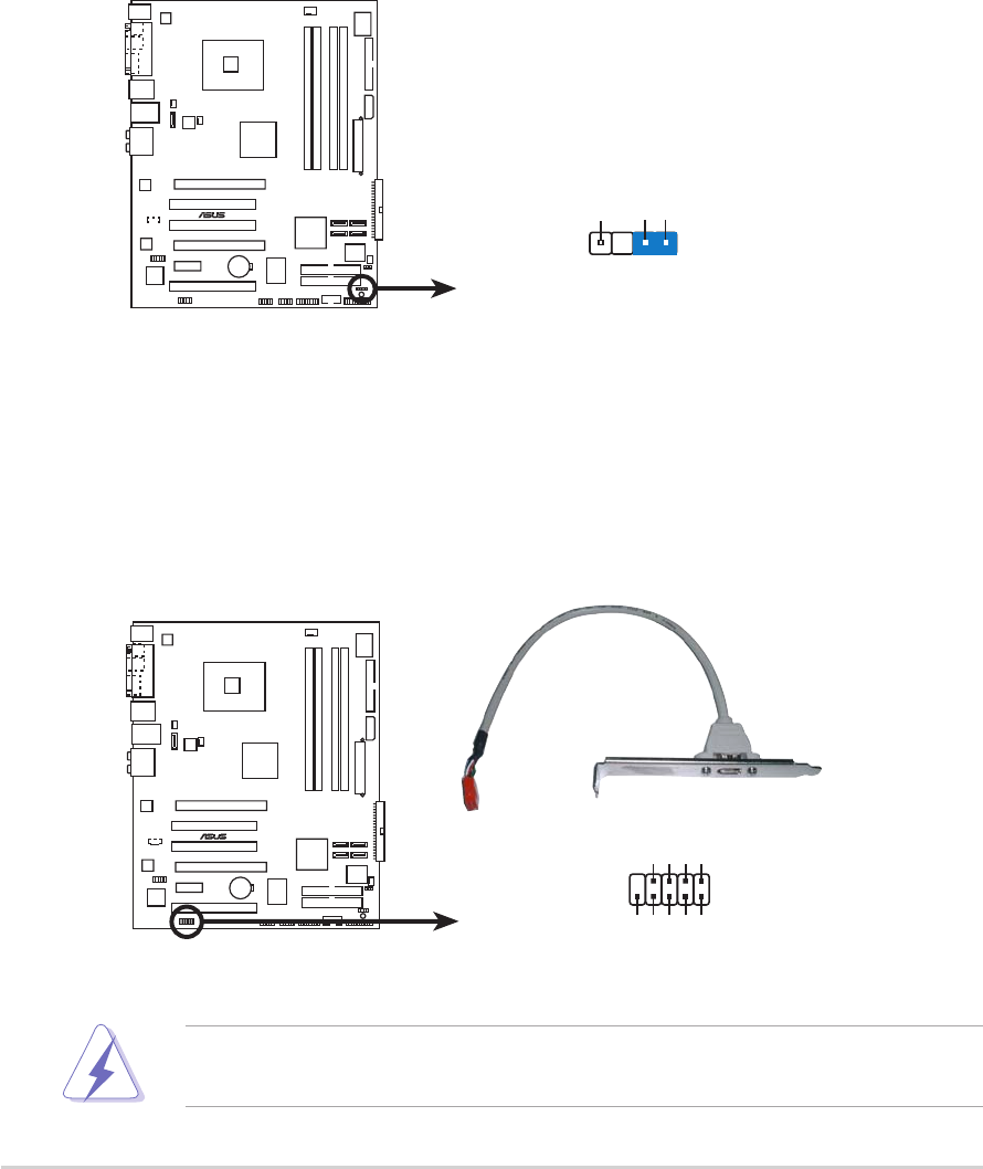
Chassis intrusion connector (4-1 pin CHASSIS)
This connector is for a chassis-mounted intrusion detection sensor or
switch. Connect one end of the chassis intrusion sensor or switch
cable to this connector. The chassis intrusion sensor or switch sends a
high-level signal to this connector when a chassis component is
removed or replaced. The signal is then generated as a chassis
intrusion event.
By default, the pins labeled “Chassis Signal” and “Ground” are shorted
with a jumper cap. Remove the jumper caps only when you intend to
use the chassis intrusion detection feature.
P5LD2 DELUXE
®
P5LD2 DELUXE Chassis intrusion connector
CHASSIS
+5VSB_MB
Chassis Signal
GND
(Default
)
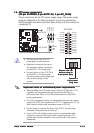
Never connect a
USB cable USB cable
USB cable USB cable
USB cable to the IEEE 1394 connectors. Doing so will
damage the motherboard!
15.15.
15.15.
15.
IEEE 1394 connector (10-1 pin IE1394_2)IEEE 1394 connector (10-1 pin IE1394_2)
IEEE 1394 connector (10-1 pin IE1394_2)IEEE 1394 connector (10-1 pin IE1394_2)
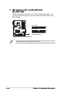
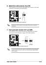
IEEE 1394 connector (10-1 pin IE1394_2)
This connector is for an additional IEEE 1394 port. Connect the IEEE
1394 module cable (orange) to this connector, then install the
module to a slot opening at the back of the system chassis.
P5LD2 DELUXE
®
P5LD2 DELUXE IEEE 1394 connector
IE1394_2
1
GND
+12V
TPB1-
GND
TPA1-
+12V
TPB1+
GND
TPA1+