


2-30 Chapter 2: Hardware information
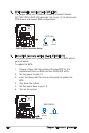
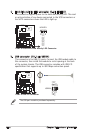
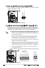
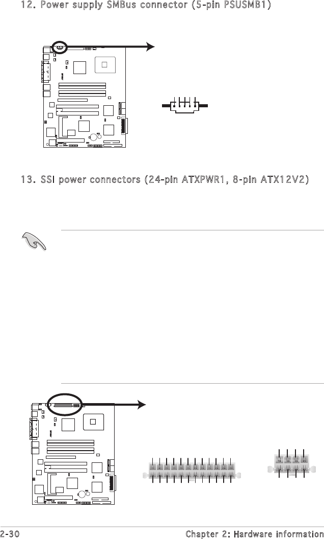
12. Power supply SMBus connector (5-pin PSUSMB1)
This connector is for the power supply SMB cable, if your power supply
supports the SMBus function.
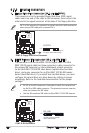
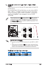
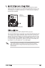
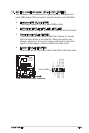
13. SSI power connectors (24-pin ATXPWR1, 8-pin ATX12V2)
These connectors are for SSI power supply plugs. The power supply plugs
are designed to fit these connectors in only one orientation. Find the proper
orientation and push down firmly until the connectors completely fit.
• Use of an SSI 12 V Specification 2.0-compliant power supply unit
(PSU) that provides a minimum power of 450 W is recommended for
a fully-configured system.
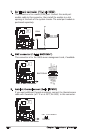
• By default, four ATX12V2 connector pins are covered to prevent
incorrent insertion of a 4-pin ATX +12V power plug. Remove this
cover when using a PSU with an 8-pin ATX +12V power plug.
• Do not forget to connect the 4-pin or 8-pin ATX +12 V power plug;
otherwise, the system will not boot up.
• We recommend that you use a PSU with a higher power output when
configuring a system with more power consuming devices. The system
may become unstable or may not boot up if the power is inadequate.
• You must install a PSU with a higher power rating if you intend to
install additional devices.
P5MT-S
®
P5MT-S Power Supply SMBus Connector
PSUSMB1
+3.3V Remote Sense
GND
NC
PSU_I2CDATA
PSU_I2CCLK
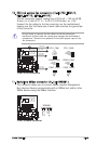
P5MT-S
ATX Power Connectors
24-pin Power Connector
ATX12V2
ATXPWR1
+3 Volts
+3 Volts
Ground
+5 Volts
+5 Volts
Ground
Ground
Power OK
+5V Standby
+12 Volts
-5 Volts
+5 Volts
+3 Volts
-12 Volts
Ground
Ground
Ground
PSON#
Ground
+5 Volts
+12 Volts
+3 Volts
+5 Volts
1
Ground
GND+12V DC
GND+12V DC
GND+12V DC
GND+12V DC
P5MT-S
®