


2-32 Chapter 2: Hardware information
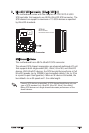
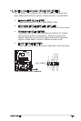
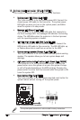
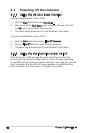
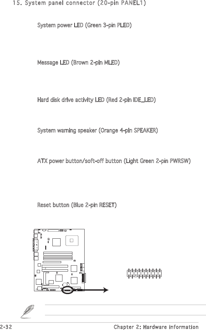
15. System panel connector (20-pin PANEL1)
This connector supports several chassis-mounted functions.
• System power LED (Green 3-pin PLED)
This 3-pin connector is for the system power LED. Connect the
chassis power LED cable to this connector. The system power
LED lights up when you turn on the system power, and blinks
when the system is in sleep mode.
• Message LED (Brown 2-pin MLED)
This connector is for the message LED cable that connects to
the front message LED. The message LED indicates the booting
status. The LED blinks when the system is in the boot process
until the operating system is loaded.
• Hard disk drive activity LED (Red 2-pin IDE_LED)
This 2-pin connector is for the HDD Activity LED. Connect the
HDD Activity LED cable to this connector. The IDE LED lights up
or flashes when data is read from or written to the HDD.
• System warning speaker (Orange 4-pin SPEAKER)
This 4-pin connector is for the chassis-mounted system warning
speaker. The speaker allows you to hear system beeps and
warnings.
• ATX power button/soft-off button (Light Green 2-pin PWRSW)
This connector is for the system power button. Pressing the
power button turns the system on or puts the system in sleep
or soft-off mode depending on the BIOS settings. Pressing the
power switch for more than four seconds while the system is ON
turns the system OFF.
• Reset button (Blue 2-pin RESET)
This 2-pin connector is for the chassis-mounted reset button for
system reboot without turning off the system power.
The system panel connector is color-coded for easy connection.
P5MT-S System Panel Connector
PANEL1
MLED-GND
NCPOWERBTN#
+5VGND
GNDNC
POWERLED+HDLED+
GNDHDLED-
POWERLED-
MLED+NMIBTN#
GNDRESETBTN#
SPKROUTGND
P5MT-S
®