


ASUS P5N73-AM 1-27
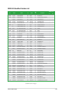
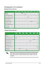
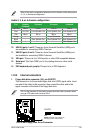
Refer to the audio conguration table below for the function of the audio ports in
2, 4, 6, or 8-channel conguration.
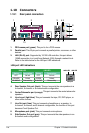
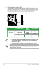
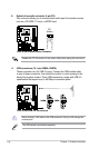
10. USB 2.0 ports 1 and 2. These two 4-pin Universal Serial Bus (USB) ports
are available for connecting USB 2.0 devices.
11. USB 2.0 ports 3 and 4.
These two 4-pin Universal Serial Bus (USB) ports
are available for connecting USB 2.0 devices.
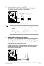
12. VGA port.
This port is for a VGA monitor or other VGA-compatible devices.
13.
Serial port. This 9-pin COM1 port is for pointing devices or other serial
devices.
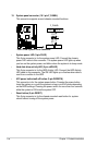
14. PS/2 keyboard port (purple).
This port is for a PS/2 keyboard.
1.10.2 Internal connectors
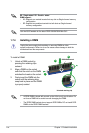
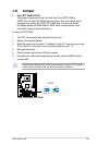
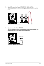
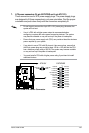
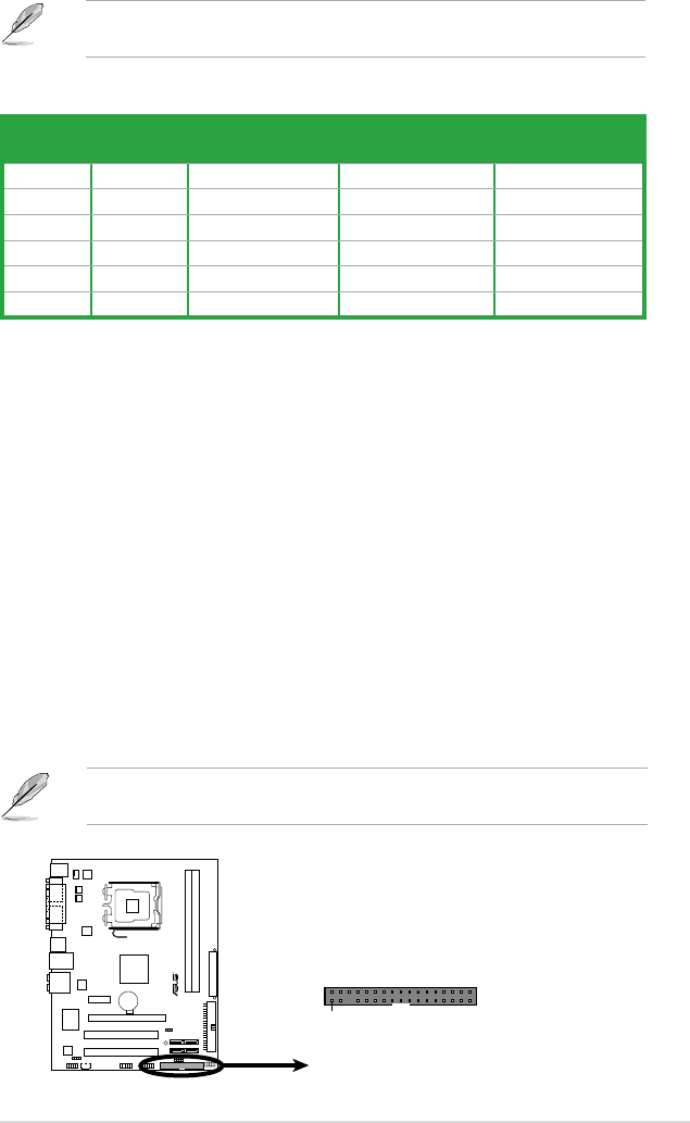
1. Floppy disk drive connector (34-1 pin FLOPPY)
This connector is for the provided oppy disk drive (FDD) signal cable. Insert
one end of the cable to this connector, then connect the other end to the
signal connector at the back of the oppy disk drive.
Pin 5 on the connector is removed to prevent incorrect cable connection when
using an FDD cable with a covered Pin 5.
Audio 2, 4, 6, or 8-channel conguration
Port Headset
2-channel
4-channel 6-channel 8-channel
Light Blue Line In Line In Line In Line In
Lime Line Out Front Speaker Out Front Speaker Out Front Speaker Out
Pink Mic In Mic In Mic In Mic In
Orange – – Center/Subwoofer Center/Subwoofer
Black – Rear Speaker Out Rear Speaker Out Rear Speaker Out
Gray – – – Side Speaker Out
P5N73-AM
R
P5N73-AM
Floppy Disk Drive Connector
NOTE:
Orient the red markings on
the floppy ribbon cable to PIN 1.
PIN1
FLOPPY