


4 ASUS P/I-XP55T2P4 User's Manual
III. INSTALLATION
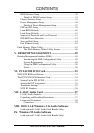
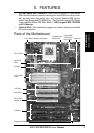
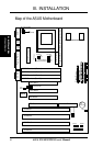
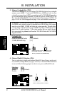
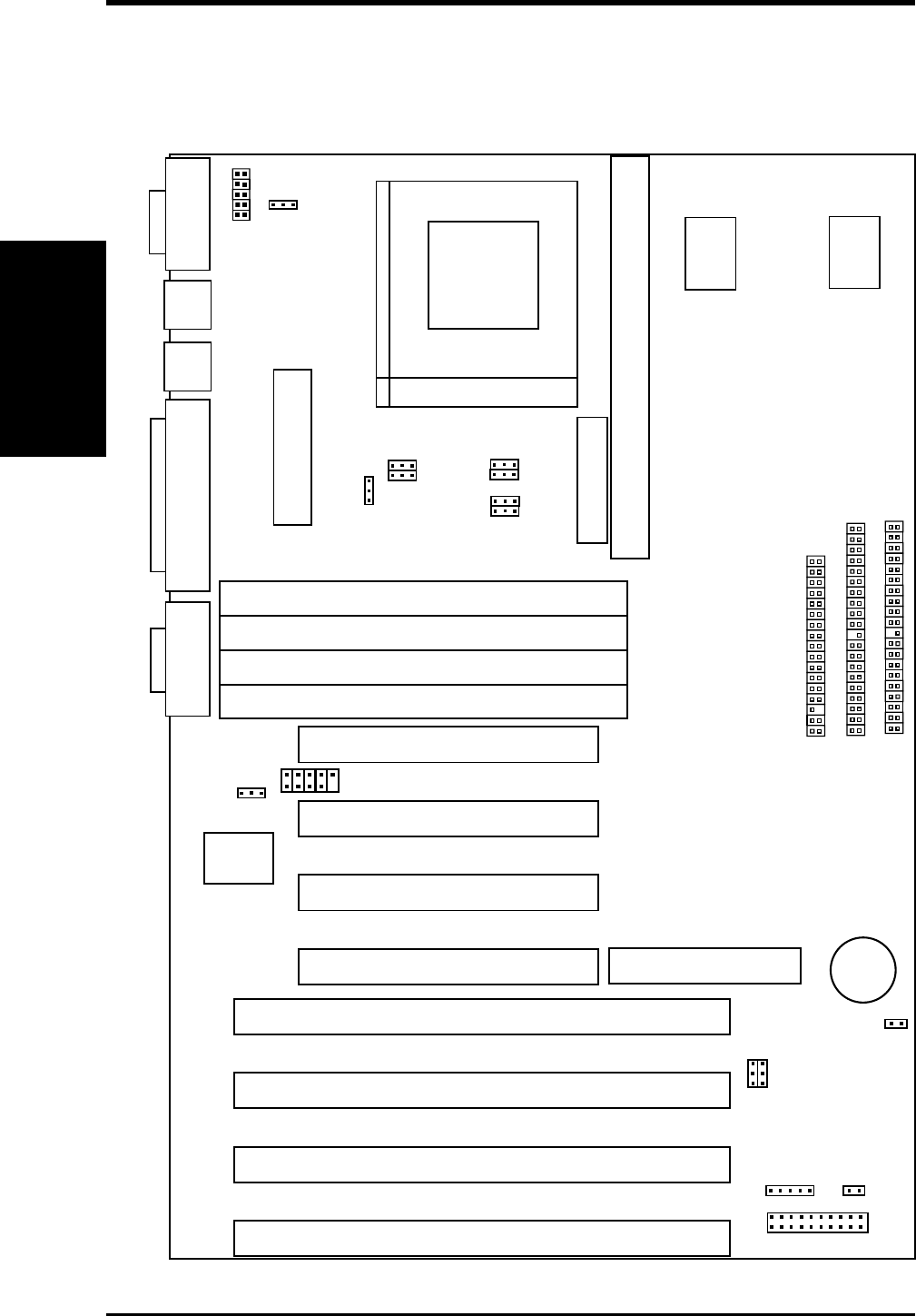
Map of the ASUS Motherboard
Floppy Drives
ISA Slot 3
ISA Slot 2
ISA Slot 1
PCI Slot 1
SIMM Socket 1 (Bank 0)
SIMM Socket 2 (Bank 0)
Pipelined Burst Level 2 Cache Expansion Slot
ISA Slot 4
SIMM Socket 3 (Bank 1)
SIMM Socket 4 (Bank 1)
Board Power Input
for ATX Power Supply
IDE LED
COM 1
PS/2
Mouse
PS/2
Key-
board
Parallel PrinterCOM 2
Case Connector
JP17
JP18
CPU ZIF Socket 7
Tag SRAM Upgrade
IR Conn
MediaBus 2.0
PCI Slot 2
PCI Slot 4
Secondary IDE
Primary IDE
PCI Slot 3
CMOS (Operate/Clear)
Block Write (Dis/En)
JP19
JP16
Multi-I/O (En/Dis)
Universal Serial Bus
Super
Multi-I/O
JP12
L2 Cache (256/512)
JP15
JP14
JP13
Memory Cached (64/512)
CPU Fan Power
Bus Freq.
JP9
JP10
Freq. Ratio
CPU Volt (STD/VRE)
JP1
CPU Vcore Volt (2.5-2.9)
2.5
2.7
2.8
2.9
Res.
256KB/512KB Onboard L2 Cache
CR2032
3 Volt
Lithium Cell
(Map of Board)
III. INSTALLATION