


12 ASUS P/I-XP55T2P4 User’s Manual
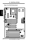
III. INSTALLATION
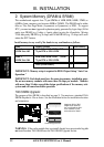
2. System Memory (DRAM & SRAM)
This motherboard supports four 72-pin SIMMs of 4MB, 8MB, 16MB, 32MB, or
64MB to form a memory size between 8MB to 256MB. The DRAM can be either
60ns or 70ns Fast Page Mode (Asymmetric or Symmetric) or EDO. To support
ECC, you must use true (opposed to phantom parity generated by logic chips) 36-bit
parity-type DRAM (e.g. 8 chips + 4 parity chips) in pairs for all modules. Mixing
32-bit non-parity DRAM (e.g. 8 chips) and 36-bit DRAM (e.g. 12 chips) will work
minus the ECC feature.
IMPORTANT: Memory setup is required in BIOS Chipset Setup "Auto Con-
figuration."
IMPORTANT: Each bank must have the same size memory installed in pairs.
Do not use memory modules with more than 24 chips per module. Modules
with more than 24 chips exceed the design specifications of the memory sub-
system and will cause unreliable operation.
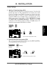
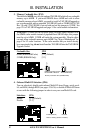
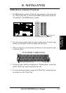
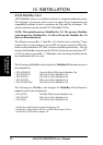
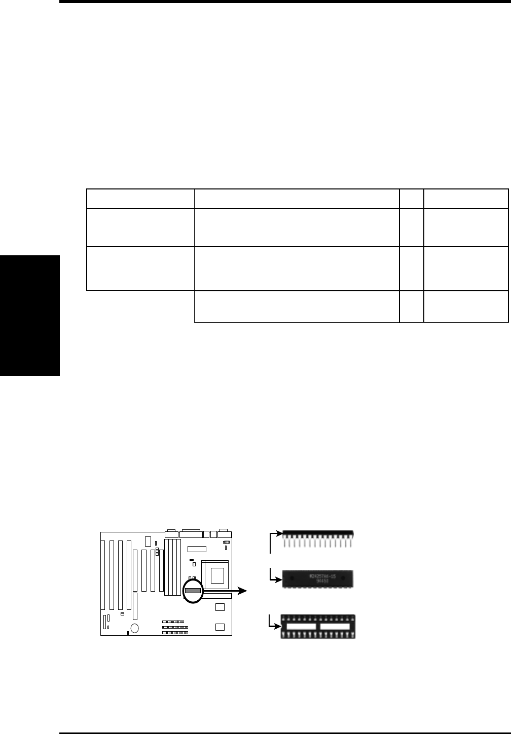
TAG SRAM Upgrade:
The purpose of this SRAM is described on page 9. You must use a standard 5Volt
SRAM chip that is 15ns or faster. See the illustration below for installation location
and orientation.
Insert one 16K8 or 32K8
SRAM chip as shown by
the Top view with the semi-
circle "Indention" on the
same side as the "Notch."
TAG SRAM Upgrade Socket
Notch
SRAM Chip Side
Indention
SRAM Chip Top
WARNING: If the cache module that you install already have an extended tag, do
not install another TAG SRAM into the TAG SRAM Upgrade Socket.
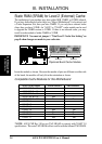
Install memory in any or all of the banks in any combination as follows:
Bank Memory Module Total Memory
Bank 0 4MB, 8MB, 16MB, 32MB, 64MB x2
SIMM Slots 1&2 72-pin FPM or EDO SIMM
Bank 1 4MB, 8MB, 16MB, 32MB , 64MB x2
SIMM Slots 3&4 72-pin FPM or EDO SIMM
Total System Memory =
III. INSTALLATION
(Memory)