


ASUS P/I-XP55T2P4 User’s Manual 23
III. INSTALLATION
(Connectors)
III. INSTALLATION
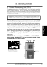
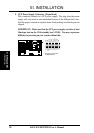
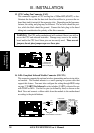
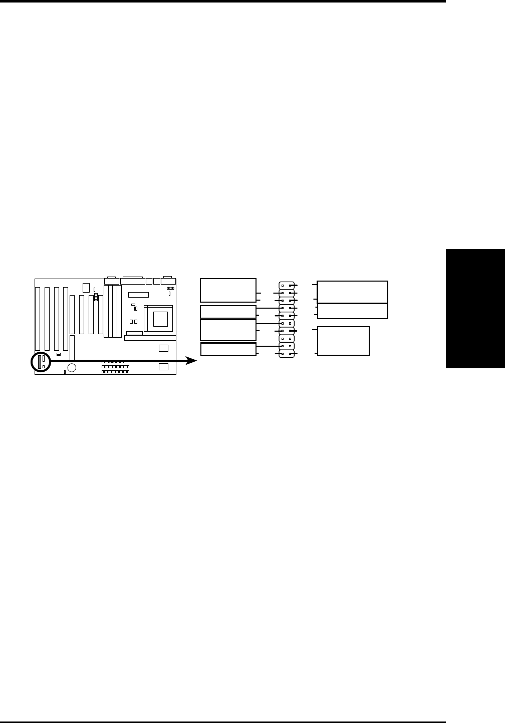
12. ATX Power Switch (CON1) (ATX Power Supply Only)
The system power is controlled by a momentary switch connected to this lead.
Pushing the button once will turn on the system and pushing another time will
turn off the system. The system power LED shows the status of the system's
power. This connection does not have a function when a standard power sup-
ply is used. See the figure below.
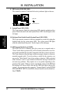
13. Reset Switch Lead (CON1)
This 2-pin connector connects to the case-mounted reset switch for rebooting
your computer without having to turn off your power switch This is a pre-
ferred method of rebooting in order to prolong the life of the system's power
supply. See the figure below.
14. Speaker Connector (CON1)
This 4-pin connector connects to the case-mounted speaker.
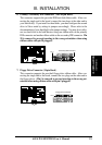
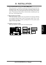
System Case Connections
+5V
NC
GND
LOCK
GND
+5V
SPKR
Speaker
Connector
GND
GND
GND
+5V
Reset SW
SMI Lead
Power LED
ATX Power
Switch
System
Power LED
Keyboard Lock
GND