


ASUS P/I-XP55T2P4 User’s Manual 21
III. INSTALLATION
(Connectors)
III. INSTALLATION
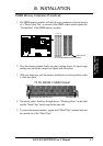
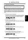
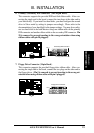
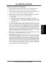
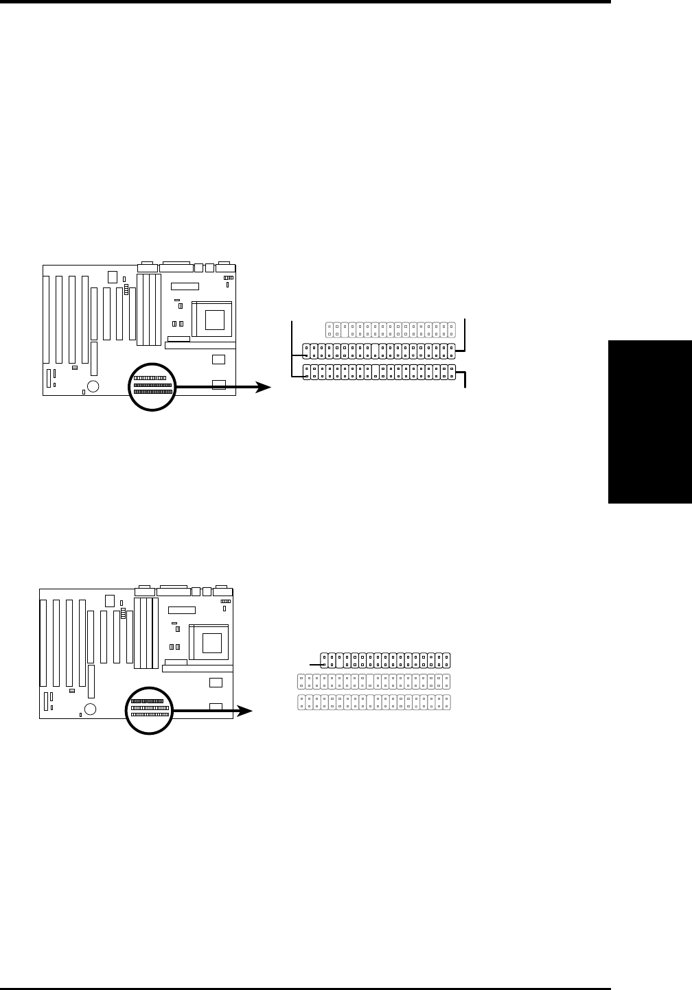
6. Primary / Secondary IDE connectors (Two 40-pin Block)
This connector supports the provided IDE hard disk ribbon cable. After con-
necting the single end to the board, connect the two plugs at the other end to
your hard disk(s). If you install two hard disks, you must configure the second
drive to Slave mode by setting its jumpers accordingly. Please refer to the
documentation of your hard disk for the jumper settings. You may also config-
ure two hard disks to be both Masters using one ribbon cable on the primary
IDE connector and another ribbon cable on the secondary IDE connector. Pin
20 is removed to prevent inserting in the wrong orientation when using
ribbon cables with pin 20 plugged).
Primary IDE Connector
Pin 1
Secondary IDE Connector
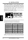
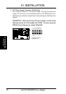
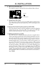
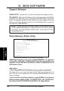
7. Floppy Drive Connector (34-pin block )
This connector supports the provided floppy drive ribbon cable. After con-
necting the single end to the board, connect the two plugs on the other end to
the floppy drives. (Pin 5 is removed to prevent inserting in the wrong ori-
entation when using ribbon cables with pin 5 plugged).
Floppy Drive Connector
Pin 1