1. Introduction
7
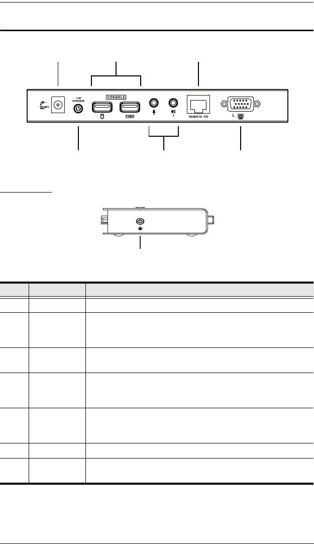
CE800BL / CE800BR Rear View
Side View
No. Component Description
1 Power Jack The cable from the DC Power Adapter plugs into this jack.
2 Keyboard and
Mouse Ports
The console USB keyboards and mice plug into these ports.
The ports are color coded and marked with an icon to identify
themselves.
3 Link Port The Cat 5e cable that connects the Remote and Local units
plugs into this connector.
4 Firmware
Upgrade Port
(Local Unit only)
The Firmware Upgrade Cable that transfers the firmware
upgrade data from the administrator's computer to the
CE800
BL plugs in here.
5Console
Audio Jacks
The stereo microphone and stereo speakers plug into these
connectors. The ports are color coded and marked with an
icon to identify themselves.
6 Video Port The console monitors plug into these ports.
7 Grounding
Terminal
The grounding wire (used to ground the unit) attaches here.
5
1 3
4
2
6
7


